R&S OSP Instrument Functions
Operating Manual 1505.3896.12 - 14 81
For cabling the options OSP-Z11 or Z12 are required. See chapter 5.1.4.3 for details.
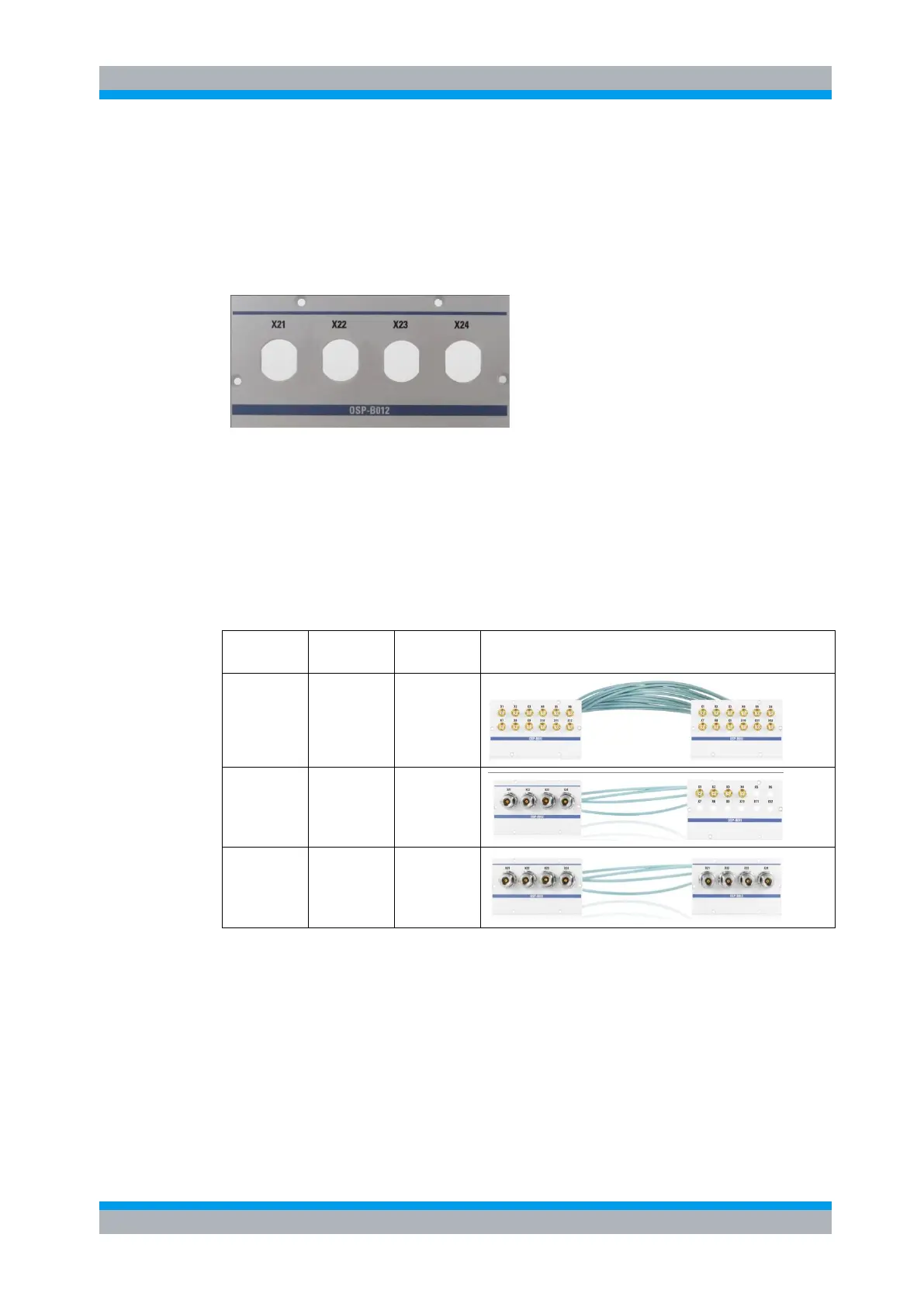
5.1.4.2 Module R&S OSP-B012
The module OSP-B012 is a panel (1-slot size) prepared to be fitted with up six coaxial
feed-through connectors N-female; see below picture.
Slot A12F Slot A13F
Figure 5-9: R&S OSP-B011 module panel
For cabling the options OSP-Z11 or Z12 are required. See chapter 5.1.4.3 for details.
5.1.4.3 Cable sets R&S OSP-Z010/-Z011/-Z012
The modules OSP-B011 and/or OSP-B012 can be connected using the cable sets and
configurations as shown in the below table.
All Cable Sets consist out of four coaxial cables fitted with suitable coaxial connectors.
The coaxial connectors are bulkhead connector types with round flange. They are fed
through the Module panels from rear-side and fixed wuth the cenztral screw.
This way it is not required to open the OSP instrument to mount the options OSP-
B010/-B011 and/or –B012 together with the related cable sets.
5.1.5 R&S OSP150 Version15 and Module Slots
The R&S OSP150 Version 15 is designed with two slots in the front side in addition to
the three slots at the rear side as described above.