R&S OSP Instrument Functions
Operating Manual 1505.3896.12 - 14 122
Pressing the key STATUS toggles the selection of the relay.
A selected relay (K1 in this example) is displayed with a green surrounding. All
selected relays are taken over into a path configuration.
A non selected relay is not considered when defining a path configuration.
5.3.10 Using the R&S OSP-B123 to R&S OSP-B126 and R&S OSP-B129
The modules R&S OSP-B123, R&S OSP-B124, R&S OSP-B125 and R&S OSP-B126
combine different numbers of SPDT and SP6T as they are used in the R&S OSP-B121
and R&S OSP-B122 module, respectively.
The module R&S OSP-B129 houses one terminated SP8T and two SPDT switches.
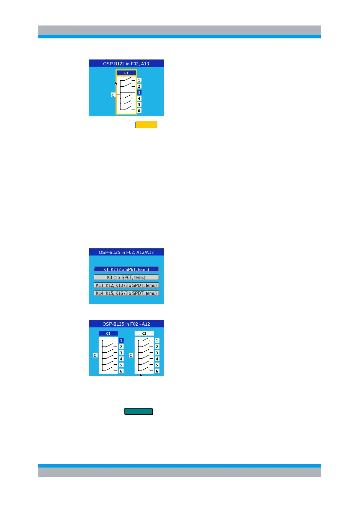
The following example is given for the module R&S OSP-B125. After selection of the
this module the following dialog is opened. This dialog shows all the available relays of
the module.
Selecting the first group of relays, a dialog is opened for relay selection and switching.
The operation is as usual. With the cursor left/right keys you can chose either relay,
and with the cursor up/down keys any terminal of that relay, indicated by the blue
color. In the example this is terminal 1 of relay K1.
Pressing the FUNCTION key closes the chosen relay position. With the Common
terminal chosen (“C” displayed in blue) the relay is opened. The display of the switch in
the dialog is changed accordingly.