R&S OSP Instrument Functions
Operating Manual 1505.3896.12 - 14 76
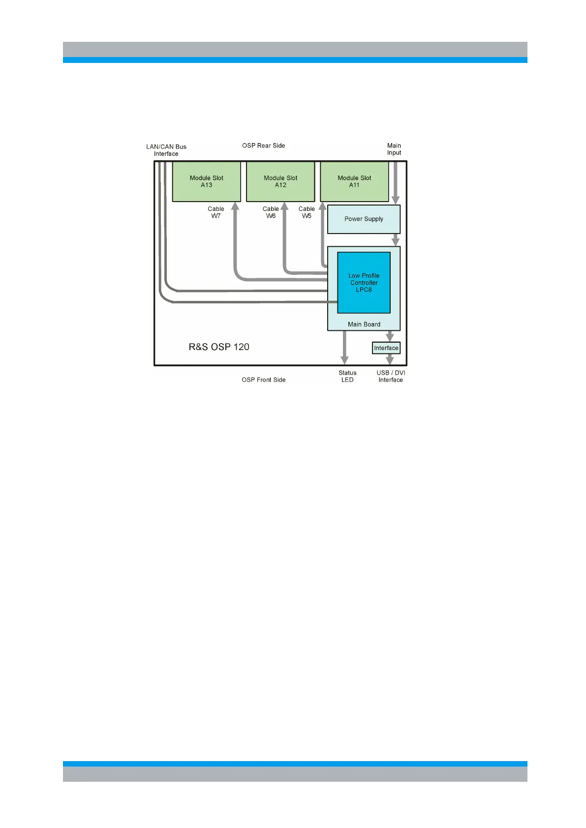
5.1.1 R&S OSP Block Diagram
The following block diagram shows the main functional groups of the R&S OSP120.
Figure 5-1: Block Diagram R&S OSP120
The central part of the R&S OSP frame is the Low Profile Controller LPC8 with Linux
Operating System. The computer handles the external interfaces of the R&S OSP120
such as LAN, USB and DVI. It also serves the internal interfaces in the R&S OSP120
like the control ports for the three slots which can take the R&S OSP modules.
The single board computer is plugged onto the R&S OSP Main Board. The basic
component on the mainboard is an FPGA which supplies all necessary interfaces
between computer PCI Bus and R&S OSP internal interfaces like the control ports for
the R&S OSP modules. The CAN bus which is used to connect further R&S OSP
extension units is implemented in the FPGA as well.
The power is supplied by a 175 W switching type power supply. The supply voltage for
the R&S OSP modules and their relays is generated by a voltage converter which is
placed on the Main Board.
Via a small interface board the connectors of the Low Profile Controller are adapted to
the standard interfaces to connect USB devices and the DVI monitor.