R&S OSP Instrument Functions
Operating Manual 1505.3896.12 - 14 120
Pressing the key OK will execute a read command. The status of the interlock, i.e. if
there is a connection between pins 7 and 15 of the IN / OUT connector, is indicated. A
green signal shows a closed interlock, a red signal an open interlock. If the interlock is
closed, a relay also closes a contact between pins 8 and 14 of the IN / OUT connector.
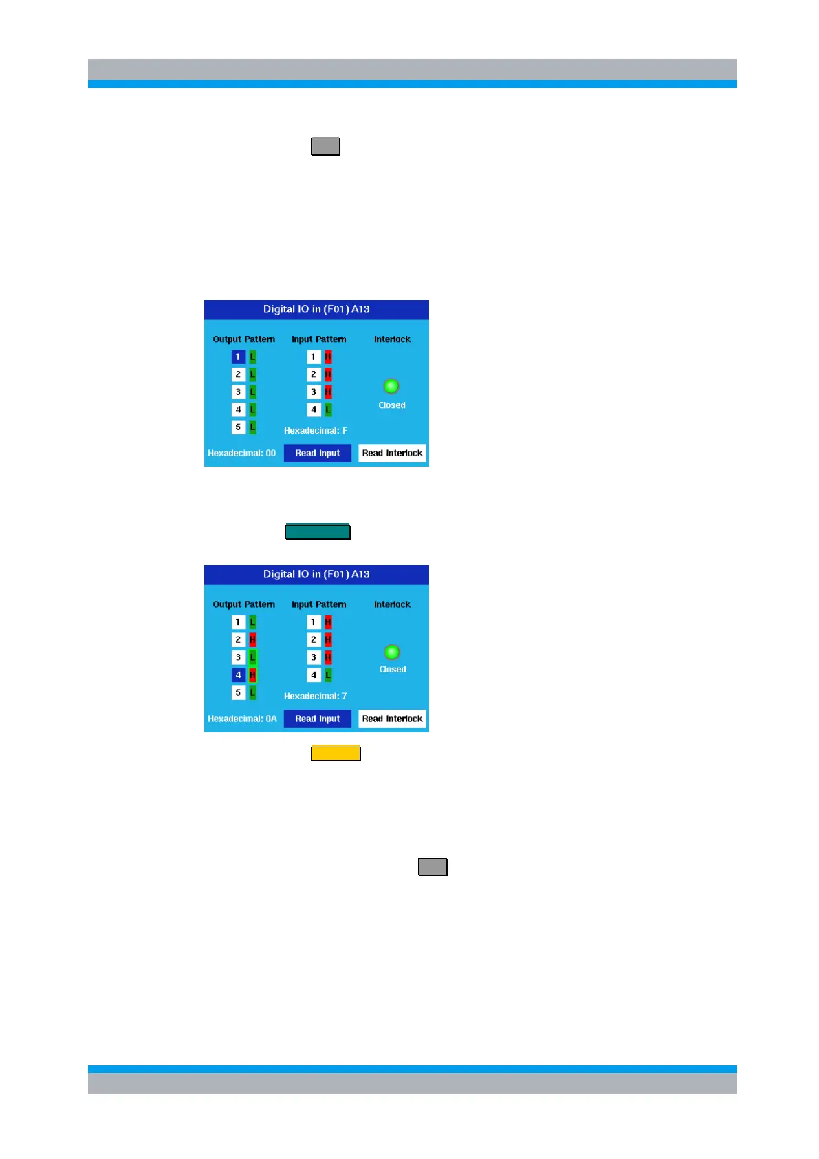
5.3.7.2 Input and Output Pattern
When the Digital I/O had been chosen, the following dialog is shown.
With the cursor up / down keys any of the 5 output channels can be chosen, indicated
by the blue color. In the example this is channel 1.
Pressing the FUNCTION key toggles this channel from low (L, dark green) to high (H,
red) and vice versa. The display of the channel in the dialog is changed accordingly.
Pressing the key STATUS toggles the selection of the channel.
A selected channel (channels 3 and 4 in this example) is displayed with a green
surrounding. All selected channels are taken over into a path configuration.
A non selected channel is not considered when defining a path configuration.
With the cursor left / right key either Read Input or Read Interlock can be selected,
indicated in blue. Pressing the key OK will execute a read command.
In the case of Read Input the status of all input channels is read. They will be
displayed in dark green for low values (L) and in red for high values (H). The case of
Read Interlock reads the interlock status, see chapter 5.3.7.1.