Operating Manual 1505.3896.12 - 14 185
For the above example, the following relay positions shall be set:
Via the OSP Panel a path configuration with the name “Path-1” is to be created. The
following steps are necessary:
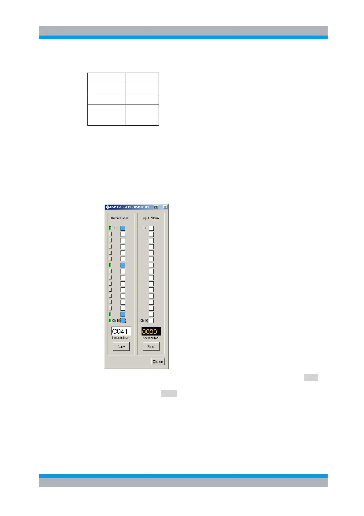
1. Start the OSP Panel, select module R&S OSP-B103 and set the required output
lines. To set relay K1/K2 and K3/K4 to position 1, the output lines Ch1 and Ch7
have to be set. For K7 and K8 in NO position, the outputs Ch15 and Ch16 are to
be set. In order to take over the setting for the R&S OSP-B103 outputs into the
path configuration, the buttons for Ch1, Ch7, Ch15 and Ch16 must be selected as
well; they are switched to green. See below dialog as example.
2. Select the utility >Path >Save Path … in the OSP Panel, Press the button Save
and enter the required name “Path-1”. The path now is stored in the R&S OSP
flash memory. Press Close to exit the dialog.