Operating Manual 1505.3896.12 - 14 64
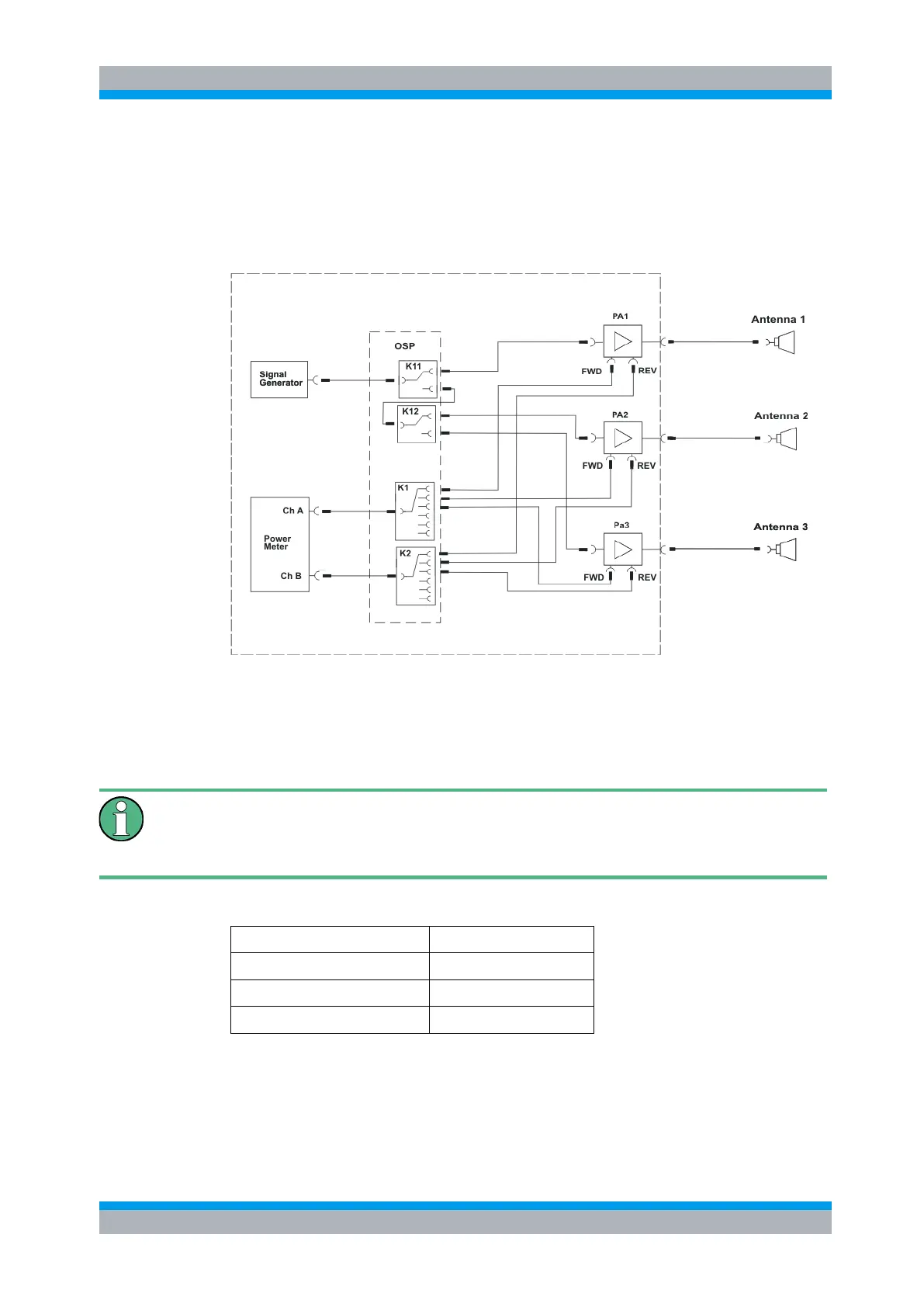
meter. The following signal paths are required and have to be set dependent on the
frequency range.
● Generator output to amplifier input
● Amplifier output forward power to power meter
● Amplifier output reverse power to power meter
3.5.1.1 Defining the Path for PA1
To have a defined condition for the path switching, it is recommended to start with the
R&S OSP in Reset condition.
Reset
To obtain the correct switching for a new path configuration, it is recommended to
reset the R&S OSP. Select in the OSP Panel >Configure >Deselect all Switches.
According to the above example, for amplifier PA1 the following paths are required:
PA1 Fwd to Power Meter Ch A
PA1 Fwd to Power Meter Ch B
Start the OSP Panel and make sure not to take over any undesired relay setting.
Select therefore in the OSP Panel >Configure >Deselect all Switches.
After that, select the OSP-B101 dialog and set K11 to position NO. Do not forget to
select the K11 button.