Operating Manual 1505.3896.12 - 14 66
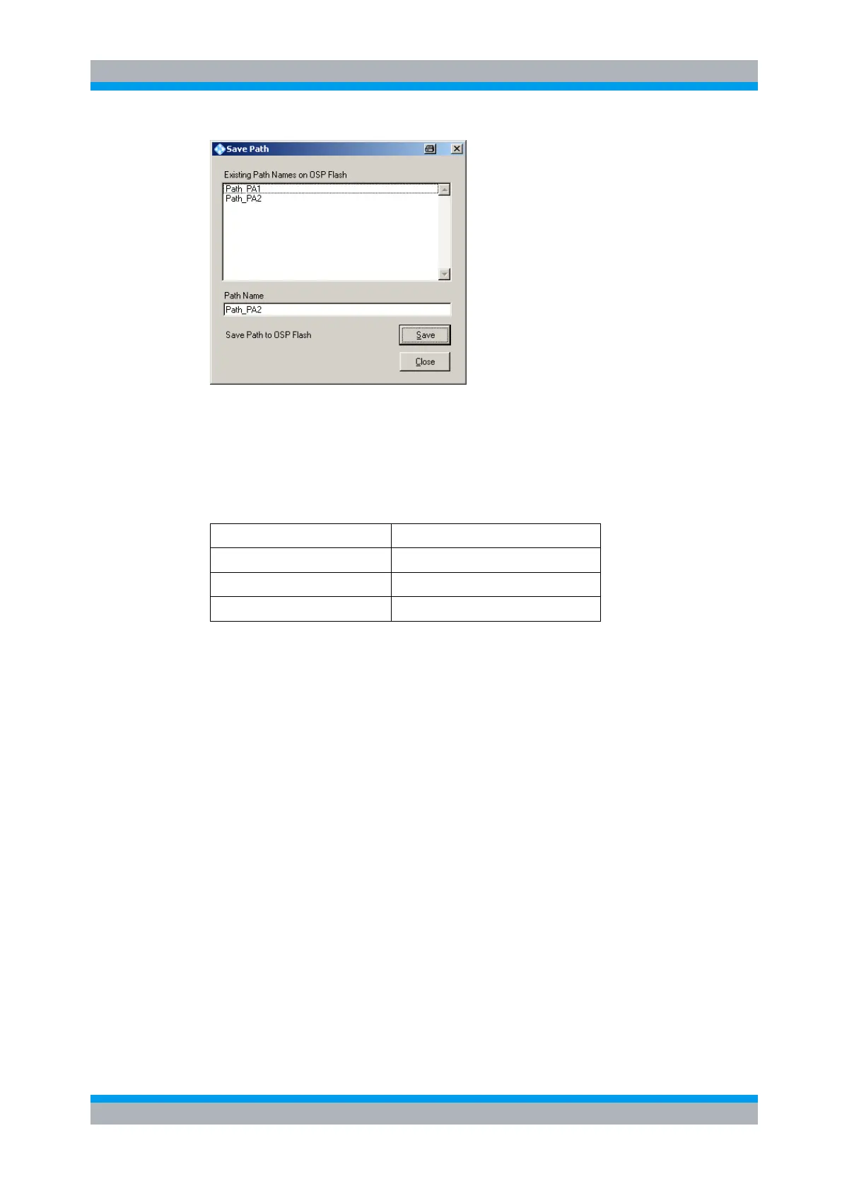
The upper data field shows the paths which are already stored in the R&S OSP. Type
in the path name “Path_PA2” and press the button “Save”.
3.5.1.3 Defining the path for PA3
According to the above example, for amplifier PA3 the following paths are required:
R&S OSP-B101 / K11- NC, K12-NC
PA3 Fwd to Power Meter Ch A
PA3 Fwd to Power Meter Ch B
Start the OSP Panel and make sure not to take over any undesired relay setting.
Select therefore in the OSP Panel >Configure >Deselect all Switches.
After that, select the OSP-B101 dialog and set K11 to position NC and K12 to position
NC. Do not forget to select the K11 and K12 buttons.
Now select the OSP-B102 dialog and set K1 and K2 to position 3. Do not forget to
select the K1 and K2 buttons.
Now start the path configuration as follows:
Select >Path >Save Path … in the OSP Panel.
The following dialog will appear: