GB
Page 22 of 60
INSTRUCTION, USE AND
MAINTENANCE MANUAL
1 2
3
1
2
1
2
3
1
2
3
4
Fig. 30
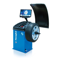
4. Fit the protection cap (Fig. 31 ref. 1) in the bush
(Fig. 31 ref. 2) and bring everything against the
wheel.
Lift the control pedal to close the mandrel and then
clamp the wheel.
Some aluminium wheels, with very high centring, must
be fitted with the cone outside the wheel.
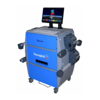
5. Clean the mandrel (Fig. 32 ref. 1) before fitting
the wheel.
6. Fit the wheel (Fig. 32 ref. 3) with the inside of the
rim towards the wheel balancer, until the wheel is
up against the support flange (Fig. 32 ref. 2).
Fig. 31
Fig. 32
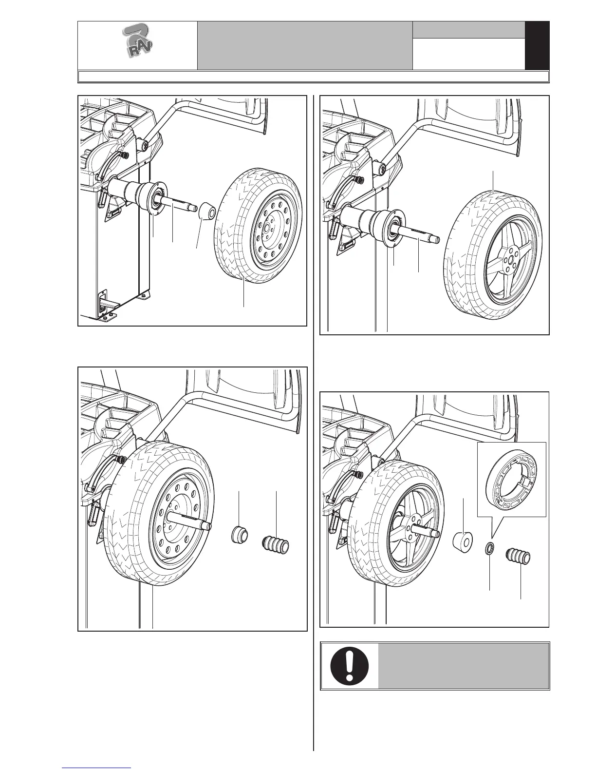
7. Fit the cone (Fig. 33 ref. 3) with the narrowest part
turned towards the wheel
8. Fit the grip-ring (Fig. 33 ref. 1) in the bush (Fig. 33
ref. 2) and bring everything against the wheel.
Fig. 33
THE GRIP-RING (FIG. 33 REF. 1)
MUST BE MOUNTED WITH THE
DISCHARGE SIDE TOWARDS THE
SLEEVE (FIG. 33 REF. 2).
Close the pneumatic mandrel by lifting the appropriate
control pedal.
G3.140R - GP3.140R - G3.140RS - GP3.140RS
RAVAGLIOLI S.p.A.
1297-M007-1_R
 Loading...