Chapter 4
18 SCS 450 Serial Interface Installation & Service Manual
Control Valve Installation
Install the Control Valve
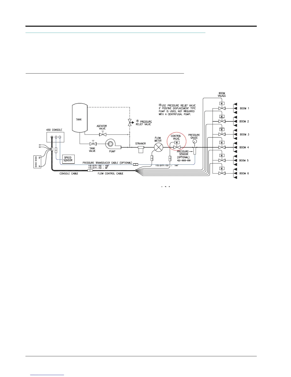
FIGURE 9. Control Valve Installation Diagram
Note: This plumbing schematic applies only to applications of 3 GPM [11 lit/min] or greater. For flow less
than 3 GPM [11 lit/min], the motorized control valve is mounted on a bypass line. Refer to the
Alternate Bypass Line Plumbing System section on page 19 for the alternate bypass line plumbing
procedure.
1. Install the control valve on the main hose line between the flow meter and the booms, with the motor in the
upright position. Refer to the diagram above.
2. Connect the yellow and green 2-pin connector of the flow control cable to the control valve.

 Loading...