4
Manual No. 016-0159-831 19
Installation
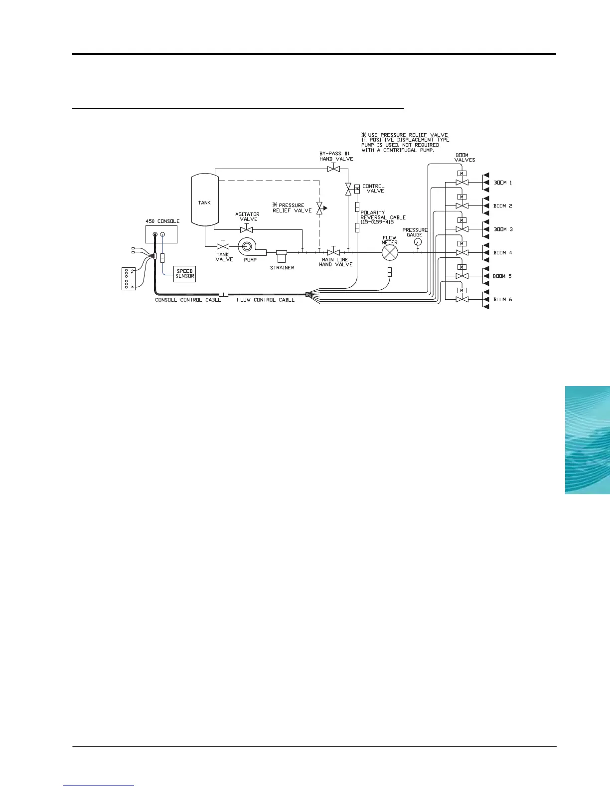
Alternate Bypass Line Plumbing System
FIGURE 10. Alternate Bypass Line Plumbing System Diagram
Note: This plumbing schematic applies only to applications of less than 3 GPM [11 lit/min]. For flow of 3
GPM [11 lit/min] or greater, the motorized control valve is installed on the main hose line. Refer to
the Install the Control Valve section on page 18 for the main hose line plumbing procedure.
1. Install the control valve in the by-pass #1 hand valve line with the motor in the upright position. Refer to the
diagram above.
2. Install the reverse polarity cable (P/N 115-0159-415) on the other end of the control valve.
3. Connect the yellow and green 2-pin connector of the flow control cable to the other end of the reverse
polarity cable.
Connect the Flow Control Cable Boom Valve Connectors
1. Connect the boom valve connector with the black signal wire to boom valve #1.
2. Connect the boom valve connector with the brown signal wire to boom valve #2
3. Connect the boom valve connector with the blue signal wire to boom valve #3.
4. Connect the boom valve connector with the black/white signal wire to boom valve #4.
5. Connect the boom valve connector with the brown/white signal wire to boom valve #5.
6. Connect the boom valve connector with the blue/white signal wire to boom valve #6.
7. Connect the boom valve connector with the white/black signal wire to boom valve #7.

 Loading...