41
APPENDIX 5
PROCEDURE TO TEST FLOW METER CABLES
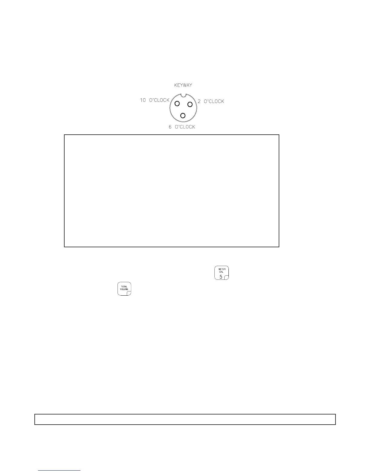
Disconnect cable from Flow Sensor. Hold Flow Sensor cable so that the keyway is pointing in the 12 o’clock
position:
PROCEDURE TO CHECK CABLE:
1) Enter a METER CAL number of one (1) in key labelled .
2) Depress key labelled .
3) Place BOOM switches to ON.
4) With small jumper wire (or paper clip), short between the 2 o’clock and 6 o’clock sockets with a
"short-no short" motion. Each time a contact is made, the TOTAL VOLUME should increase by
increments of 1 or more counts.
5) If TOTAL VOLUME does not increase, remove the section of cable and repeat test at connector
next closest to Console. Replace defective cable as required.
6) Perform above voltage checks.
7) If all cables test good, replace Flow Sensor.
NOTE: After testing is complete, re-enter correct METER CAL numbers before application.
PIN DESIGNATIONS
2 o’clock socket location is ground.
10 o’clock socket location is power.
6 o’clock socket location is signal.
VOLTAGE READINGS
1) 2 o’clock socket to 6 o’clock socket = +5 VDC.
2) 2 o’clock socket to 10 o’clock socket = +5 VDC.
If a +5 VDC voltage reading is not present, disconnect the Speed
Sensor cable. If the Flow reading is restored, Test the Speed
Sensor cable per Appendix "PROCEDURE TO TEST SPEED
SENSOR EXTENSION CABLES".

 Loading...