RAYFace 2. Product Introduction
14
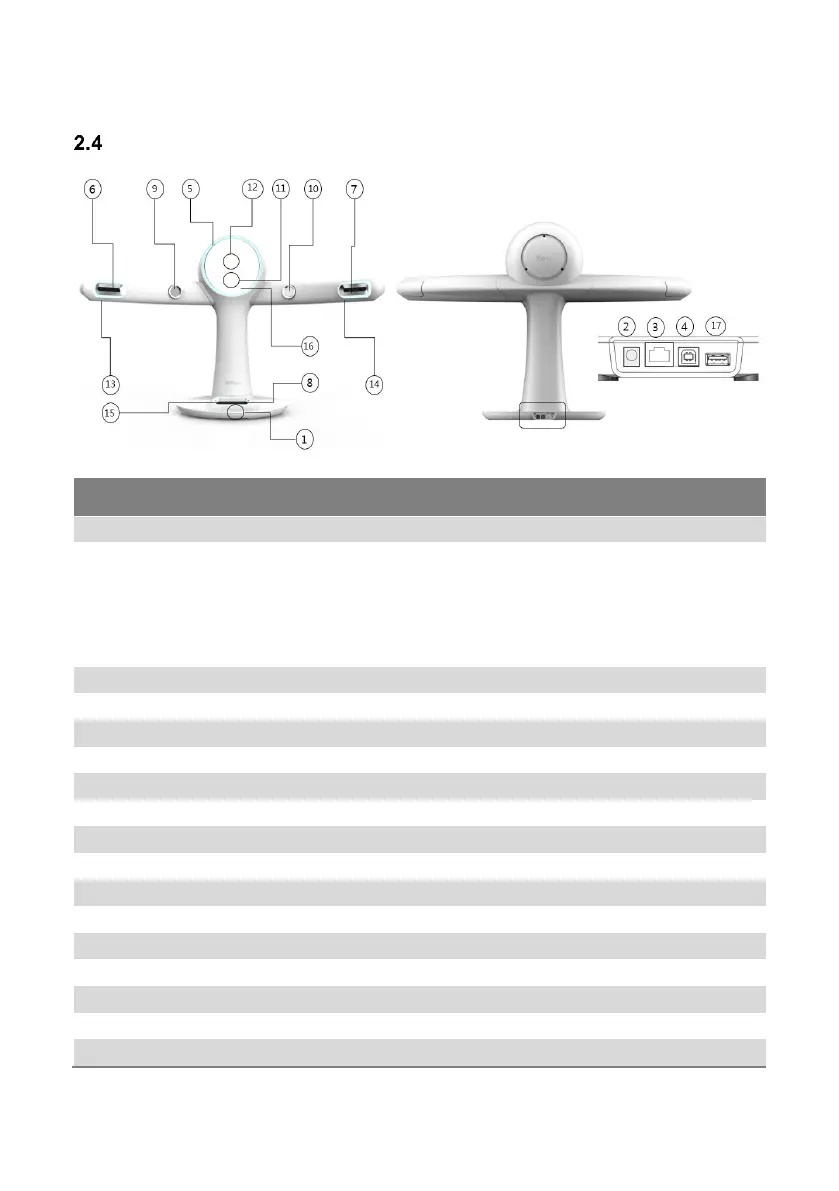
Sections and Functions (Scanner Body)
[Front] [Rear]
Main power On/Off switch.
Terminal to connect the AC adapter plug. Connect one side
of the power cord to the AC adapter before connecting to
the outlet.
Attention: The power cord type may differ depending
on the region.
Warning: Do not use other AC adapters.
Port for the RAYFace setup during installation.
Port to connect an ethernet cable.
LED to indicate the equipment status.
Camera to scan an image from the left.
Camera to scan an image from the right.
Camera to scan an image from the bottom.
Camera to scan the left side of the teeth.
Camera to scan the right side of the teeth.
Projector to project a Scan Pattern.
Camera to scan an image from the front.
LED lighting for a subject’s left side of the face.
LED lighting for a subject’s right side of the face.
LED lighting for a subject’s lower side of the face.
Mirror where a subject can check his or her appearance.
Port to connect the Calibration kit.