Wuhan Raycus Fiber Laser Technologies Co., Ltd
User Guide of Global Version 2000 W CW laser
Raycus User Guide | Using the Product
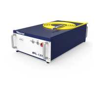
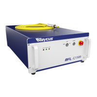
Table 7 Power connection requirements
RFL-C2000S-CE/RFL-C2000H-CE
Three strands, marked L, N and PE respectively
L->Phase line (brown)
N
-
>Neutral (blue)
PE->Protective earth wire (yellow green)
Insert the plug at the end of the power cord into the socket marked "AC INPUT"
on the rear panel. Note that the plug has anti-reverse connection function. After
plugging it in, lock it with a lock.
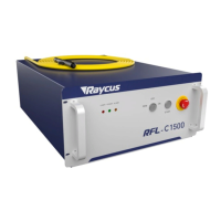
4.4 Interface definition
4.4.1 Control interface
Figure 6 shows the DB25 control interface diagram:
Figure 6 DB25 control interface
The pin definitions of DB25 are as follows: