36
e) Set out the light parameter;
f) Click “laser ON”.
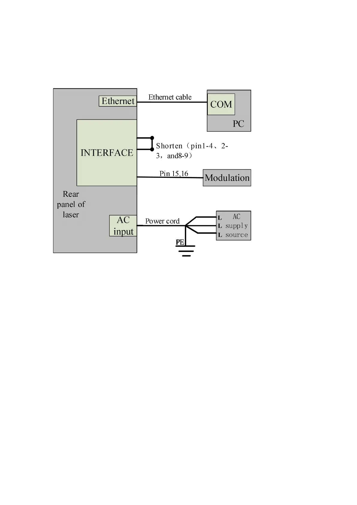
4.8.2.2 Internal/external modulation modes for power and communication
Figure 20 Wiring diagram of internal power control and external signal control
Operation method:
a) Shortconnect the 8 and 9 pins on the INTERFACE 24 pins (the control board is
powered on);
b) Open the laser clientware;
c) Click “the guide laser ON” button to view the guide laser;
d) Disabling the AD mode and the external envelopes
。
e) Waiting “Ready”;
f) Setting laser power parameters;