36
4.8.2.1 Internal control in ON mode
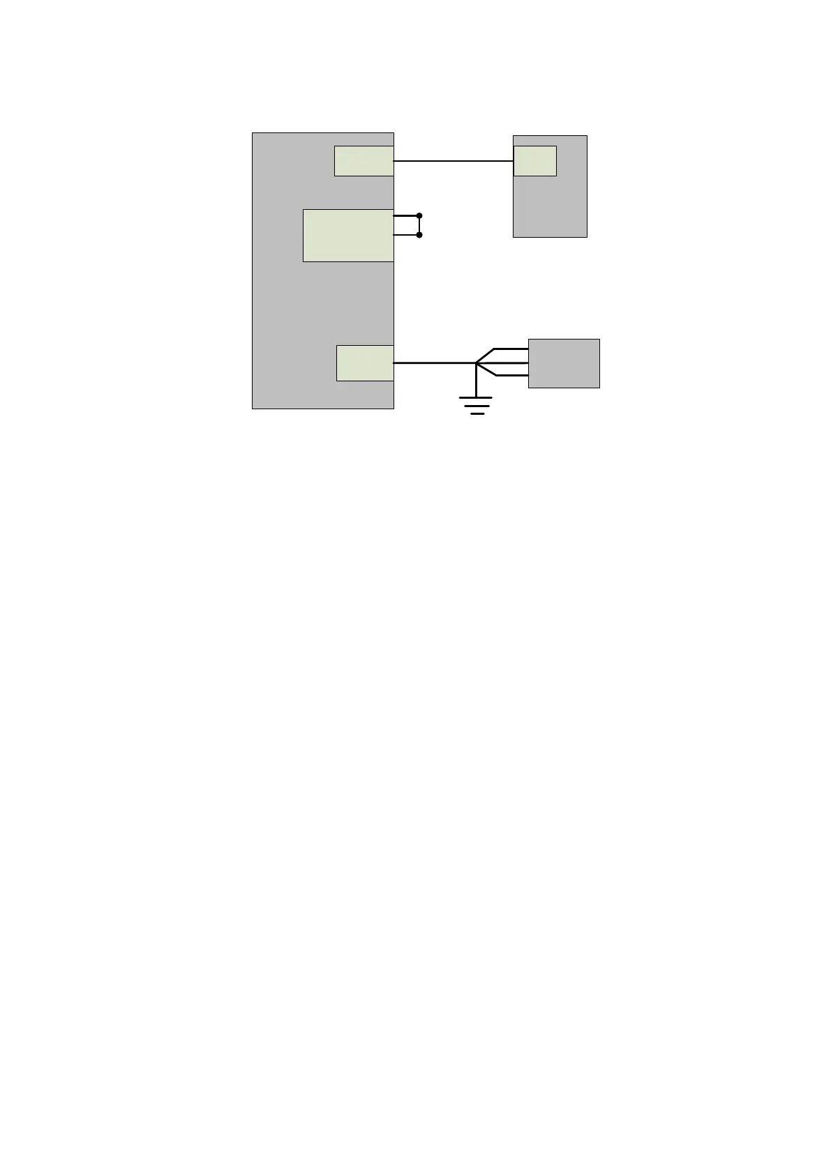
Ethernet
INTERLOCK
AC input
Rear
panel of
laser
PC
COM
Shorten(pin
1-4,and pin
2-3)
Ethernet cable
Power cord
AC
supply
source
L
PE
L
L
Figure 23 Internal control wiring diagram in key switch "ON" and clientware mode
Operation method:
a) Spring the ―ESTOP‖ knob on the front panel;
b) Key turning ―ON‖;
c) Open the laser clientware;
d) Click ―the guide laser ON‖ button to view the guide laser;
e) Disabling the AD mode\external enable\internal modulation mode and external
modulation mode;
f) Click ON ―the main power ON‖;
g) Waiting ―Ready‖;
h) Setting laser parameters;
i) Click ―laser ON‖.
4.8.2.2 Internal/external modulation modes for power and communication in REM mode