Wuhan Raycus Fiber Laser Technologies Co., Ltd.
User Guide of RFL- RFL-C6600S
37
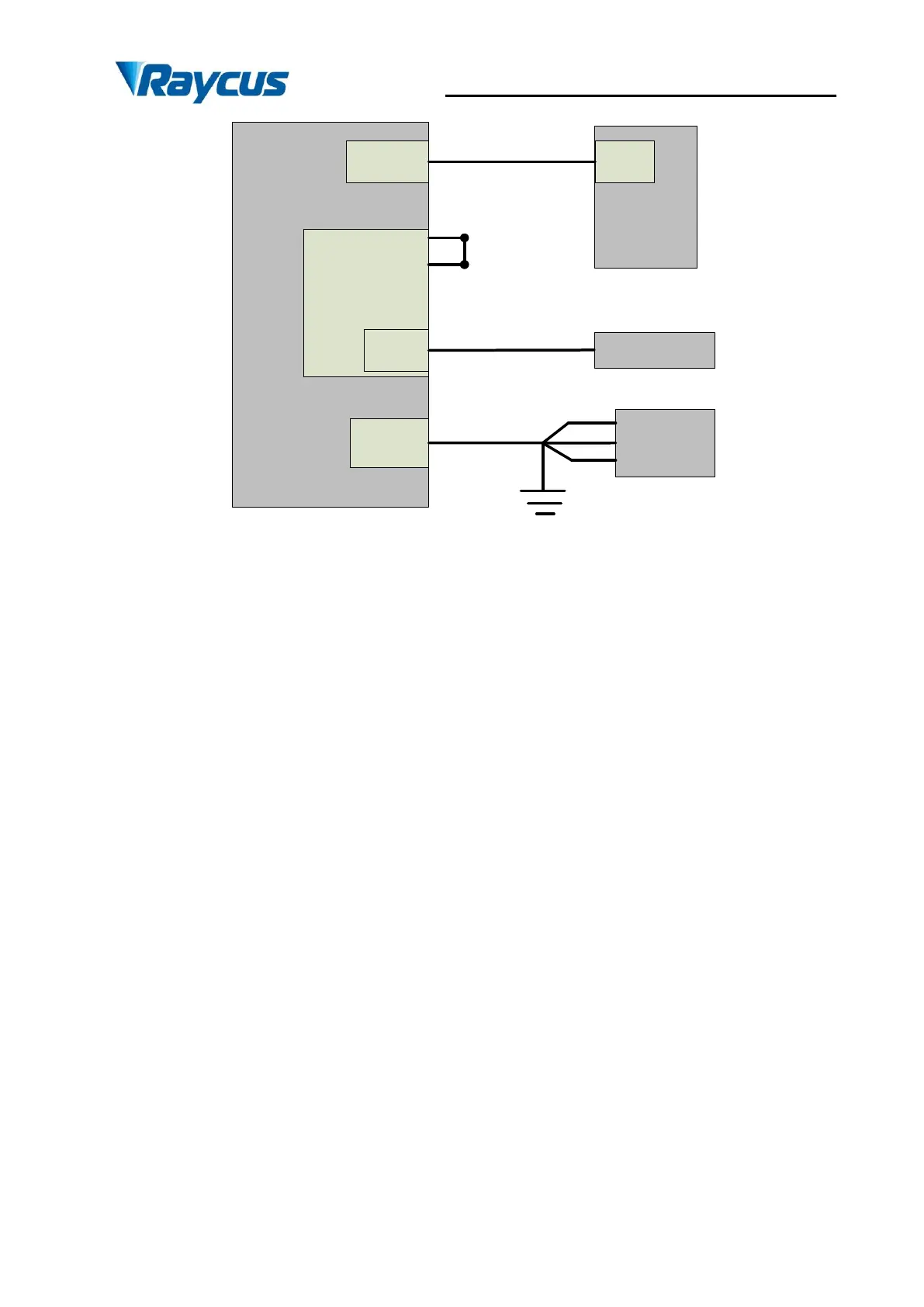
Ethernet
INTERLOCK
MOD
AC input
Rear
panel
of
laser
PC
COM
Shorten(pin
1-4,2-3)
Modulation
Ethernet cable
Pin 15,16
Power cord
AC
supply
source
L
PE
L
L
Figure 24 Wiring diagram of internal power control and external signal control in REM mode
Operation method:
a) Spring the ―ESTOP‖ knob on the front panel;
b) Key turning ―ON‖;
c) Shortconnect the 8 and 9 pins on the INTERFACE 24 pins (the control board is powered
on);
d) Open the laser clientware;
e) Click ―the guide laser ON‖ button to view the guide laser;
f) Disabling the AD mode and the external enable, and opening the internal modulation mode
or external modulation mode;
g) Click ON ―the main power ON‖;
h) Waiting ―Ready‖;
i) Setting laser power parameters;
j) On modulate mode set the frequency, duty cycle, and pulse width;(The laser is determined
by the 15.16 pin modulation signal and frequency and duty cycle);
k) Modulation signal (15, and 16-pin) provide a high level to turn on the laser.