possibleshadowedareas.Thisinformationshould
bepostednearthedisplayunitandoperatorsmust
bealertfortargetsintheseblindareas.
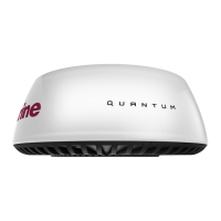
Radarscannermountingangle
EnsuretheRadarscannerrotatesparalleltothe
waterline.
TheRadarbeamfromtheRadarscanneris
approximately20°wideintheverticaldirection,to
givegoodtargetdetectionevenwhenyourvessel
pitchesandrolls.
Planinghullvessels,andsomedisplacementhull
vessels,adoptahigherbowanglewhenthevesselis
atcruisingspeed.ThismayraisetheRadar’smain
radiationangle,andcancausepoordetectionof
nearbytargets.Itmaybenecessarytocompensate
forthebowrisetoensureoptimumtargetdetection.
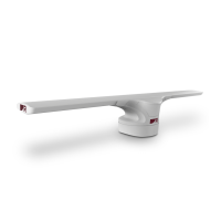
Thiscanbeachievedbyttingawedgeorwashers
betweenthemountingplatformandthebaseofthe
Radarscanner,sothattheRadarbeamremains
paralleltothewaterlinewhenthevessel'sbowrises
atcruisingspeed.
ItemDescription
1Wedgeorwashers
MultipleRadarscanners—location
requirements
Importantlocationconsiderationswheninstalling
multipleradarscannersonthesamevessel.
•Scannersshouldbemountedaboveeachother,
verticallyseparatedbyatleast0.5m(1.6ft).This
appliestoallinstallationlocationsonthevessel.
•Multiplescannersshouldbemountedinaway
thatminimizesinterferencebetweenthevertical
beamwidthsofthe2scanners.
•Inallcases,youshouldaimtoachieveasmuch
physicalseparationaspossible,tominimizeany
potentialinterference.
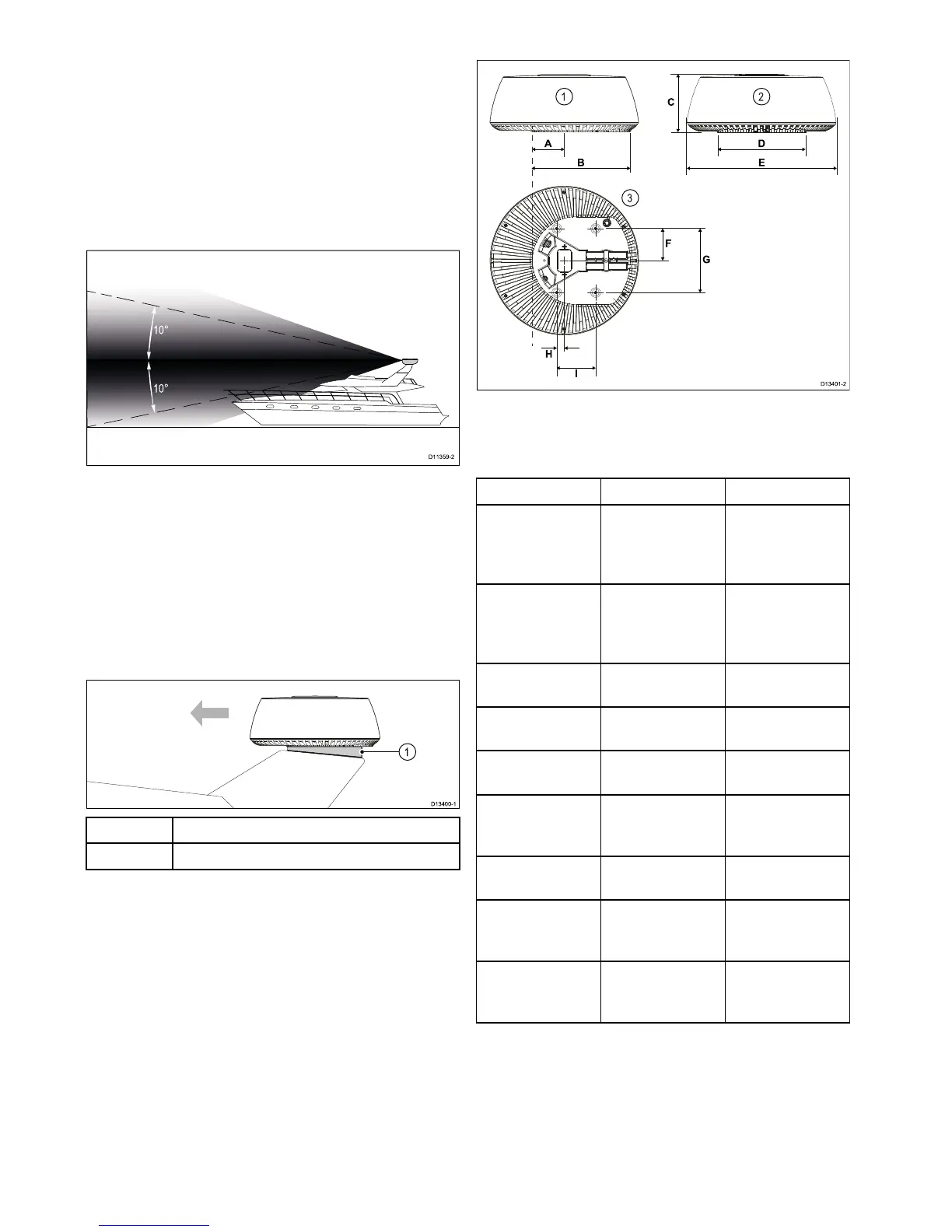
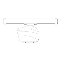
3.8Productdimensions
1.Sideviewofscanner.
2.Rearviewofscanner.
3.Undersideviewofscanner.
DimensionMeasurementDescription
A
116.0mm(4.57
in.)
Distancefrom
centerlineof
scannertofront
ofmountingbase.
B355.0mm
(13.98in.)
Distancefromrear
ofmountingbase
tofrontofmounting
base.
C
209.5mm
(8.25in.)
Heightofradar
scanner.
D319.5mm
(12.58in.)
Mountingbase
width(rearofunit).
E541.0mm
(21.30in.)
Widthofscanner.
F
116.5mm(4.59in.)Distancefrom
centerlinetorear
mountinghole.
G
233.0mm
(9.17in.)
Distancebetween
mountingholes.
H
27.5mm(1.08in.)Distancefrom
centerlinetofront
mountinghole.
I141.5mm
(5.57in.)
Distancebetween
frontandrear
mountingholes.
20
QuantumRadome