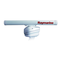
Typicalcableroutingscenarios
Thereare4typicalcableroutingscenarios.
Note:Theroutingoptionsdescribedandillustrated
inthissectionassumethataphysicaldata
connectionisusedbetweenyourRadarscanner
andmultifunctiondisplay(MFD).However,ifthe
scannerisconnectedtoyourMFDviaWi-Fi,a
physicalRayNetconnectionisnotrequired.
1.Cableroutingforascannermountedona
platform,usingseparatecablesforthepower
anddataconnection.
2.Cableroutingforascannermountedona
platform,usingthecombinedpoweranddata
cablefromanexistingRaymarineDigitalRadar
scannerinstallation.Forthis,theA80308
Y-adapteraccessoryisrequired(notsupplied
withthescanner).
3.Cableroutingforascannermountedonapole,
usingseparatecablesforthepoweranddata
connection.
4.Cableroutingforascannermountedonapole,
usingthecombinedpoweranddatacablefrom
anexistingRaymarineDigitalRadarscanner
installation.Forthis,theA80308Y-adapter
accessoryisrequired(notsuppliedwiththe
scanner).
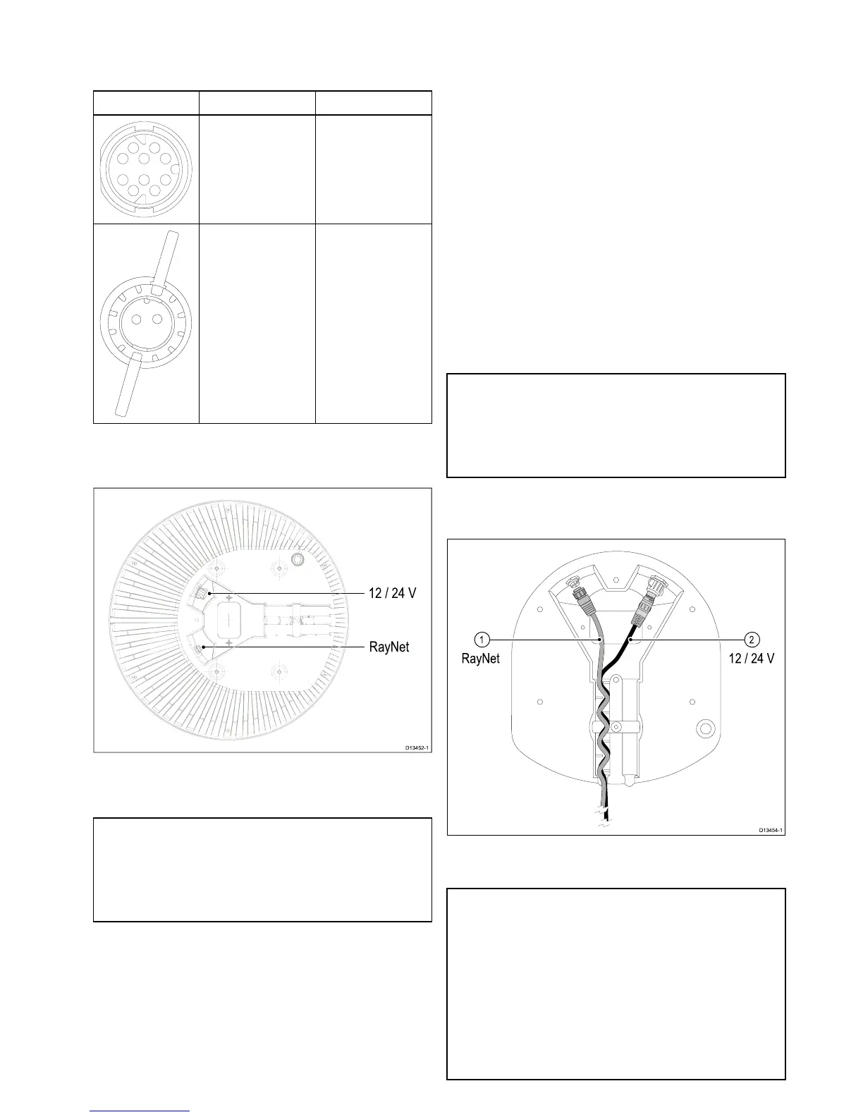
Cablerouting—platformmount
Thereare2typicalcableroutingscenariosfor
platformmountinstallations.
•Usingseparatepoweranddatacables.
•Usinganexistingcombinedpower/datacable
fromanolderRaymarineDigitalradarscanner.In
thisscenario,theA80308Y-adapteraccessoryis
required(notsuppliedwiththescanner).
Usingseparatepoweranddatacables
Note:Theroutingoptionsdescribedandillustrated
inthissectionassumethataphysicaldata
connectionisusedbetweenyourRadarscanner
andmultifunctiondisplay(MFD).However,ifthe
scannerisconnectedtoyourMFDviaWi-Fi,a
physicalRayNetconnectionisnotrequired.
Thefollowingdrawingillustratesthecableroutingfor
ascannermountedonaplatform,usingseparate
cablesforthepoweranddataconnections.