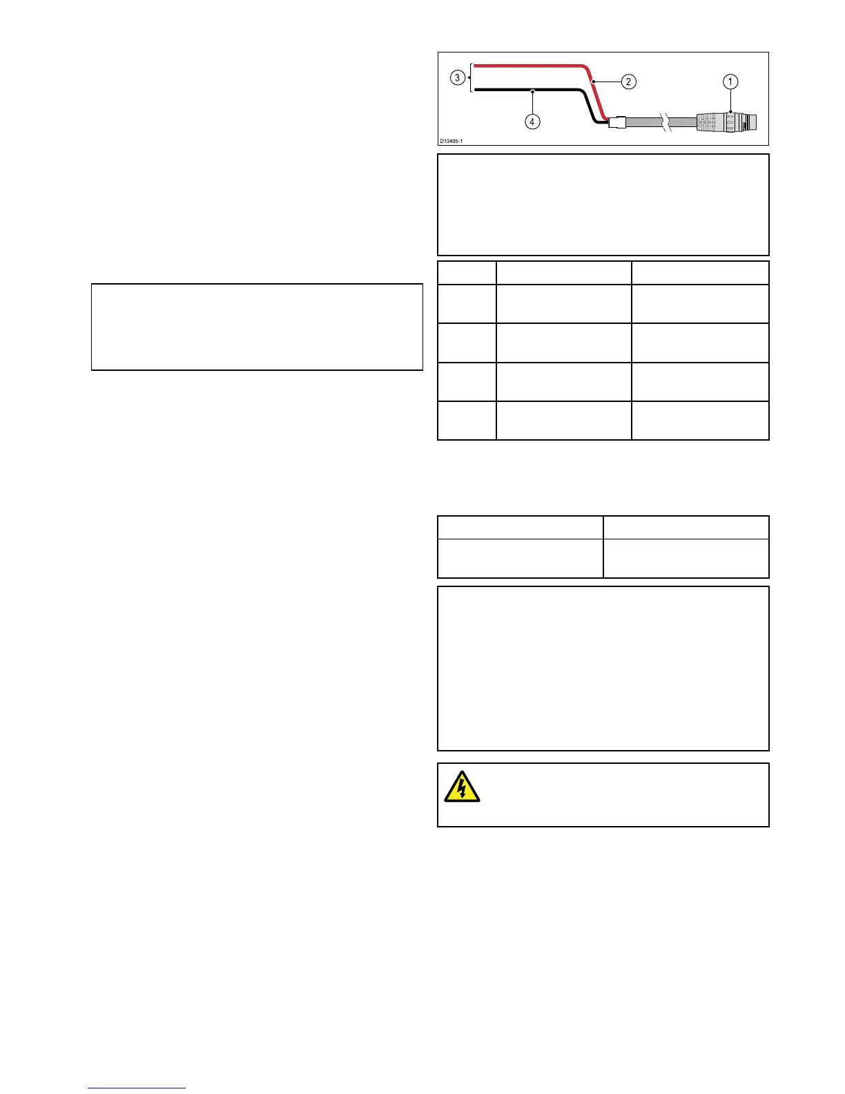
1.RayNetdataconnection.Thiscableispartof
theA80308Y-adapteraccessorycable.
2.12V/24Vpowerconnection.Thiscableispart
oftheA80308Y-adapteraccessorycable.
3.A80308Y-adapteraccessorycable(notsupplied
withthescanner).
4.ExistingcombinedDigitalRadarpower/data
cable.
Makingconnections
Followthestepsbelowtoconnectthecable(s)to
yourproduct.Ifyouintendtousethescanner’sWi-Fi
functionalitytoconnecttoyourmultifunctiondisplay,
youneedonlyconnectapowercabletothescanner.
Note:Ifyourvesselisalreadyttedwitha
combinedpower/dataDigitalRadarcable,you
canuseaY-adapter(partnumberA80308)to
connecttheexistingcable-endtothescanner’s
connectors.
1.Ensurethatthevessel'spowersupplyisswitched
off.
2.Ensurethatthemultifunctiondisplaybeing
connectedtothescannerhasbeeninstalled
inaccordancewiththeinstallationinstructions
suppliedwiththatdevice.
3.Ensurethepowerconnectorlockingcollaronthe
scannerisintheunlockedposition.
4.Routethepowercableandoptionaldatacable
withinthescannerbase,asshowninthecable
routingillustrationsinthissection.Cablerouting
dependsonwhetheryoumountthescanneron
aplatformoronapole,andonwhetheryou
areusingaY-adaptertoconnecttoanexisting
combinedpower/dataDigitalRadarcable.
5.Ensurethatthepowercableconnectoris
orientatedsothatthenotchlinesupwiththe
guideintheconnector.
6.Pushthepowercableconnectorallthewayinto
thescanner’spowerconnector.
7.Rotatethelockingcollarclockwiseuntilitisinthe
lockedposition(2clicks).
8.Pushtheoptionaldatacablefullyontothe
correspondingconnectoronthescanner.
9.IfyouareusingaY-adapter,makethenal
connectionbetweentheadapterandtheexisting
combinedpower/dataDigitalRadarcable.
4.3Powerconnection
Note:AY-adaptercable(partnumberA80308)is
availableforexistinginstallationsthatalreadyuse
acombinedpower/datacablefromaDigitalorHD
ColorRadome.TheY-adaptersplitstheexisting
combinedcableintotheseparatedataandpower
connectorsusedbythescanner.
ItemDescriptionConnectsto:
1Powercable.Product’spower
connector.
2
Redcable(positive)
Powersupply’spositive
terminal.
3
Connectionto12V/
24Vpowersupply.
Powersupply.
4
Blackcable(negative)
Powersupply’snegative
terminal.
In-linefuseandthermalbreakerratings
Thefollowingin-linefuseandthermalbreakerratings
applytoyourproduct:
In-linefuseratingThermalbreakerrating
5A
3A(ifonlyconnectingone
device)
Note:
•Thesuitablefuseratingforthethermalbreaker
isdependentonthenumberofdevicesyouare
connecting.Ifindoubtconsultanauthorized
Raymarinedealer.
•Yourproduct’spowercablemayhaveatted
in-linefuse,ifnotthenyoumustaddanin-line
fuse/breakertothepositivewireofyour
productspowerconnection.
Warning:Groundingnotrequired
Thisproductisfullyinsulatedanddoes
NOTrequireseparategrounding.
Powercableextension
Theproductissuppliedwithapowercable,which
canbeextendedifrequired.
•Thepowercableforeachunitinyoursystem
shouldberunasaseparate,singlelengthof
2-wirecablefromtheunittothevessel'sbatteryor
distributionpanel.
•Raymarinerecommendsaminimumwiregauge
of14AWG(2.08mm
2
)foranylengthofcable
extension.
•Foralllengthsofextensiontothepowercable,
ensurethereisacontinuousminimumvoltage
Cablesandconnections25