5.1Mountingthescanner
Useamountinglocationthat:
•IsrobustenoughtosupporttheQuantum™
scanner,underseagoingconditions.
•MeetstherequirementsdescribedunderScanner
Position
Then:
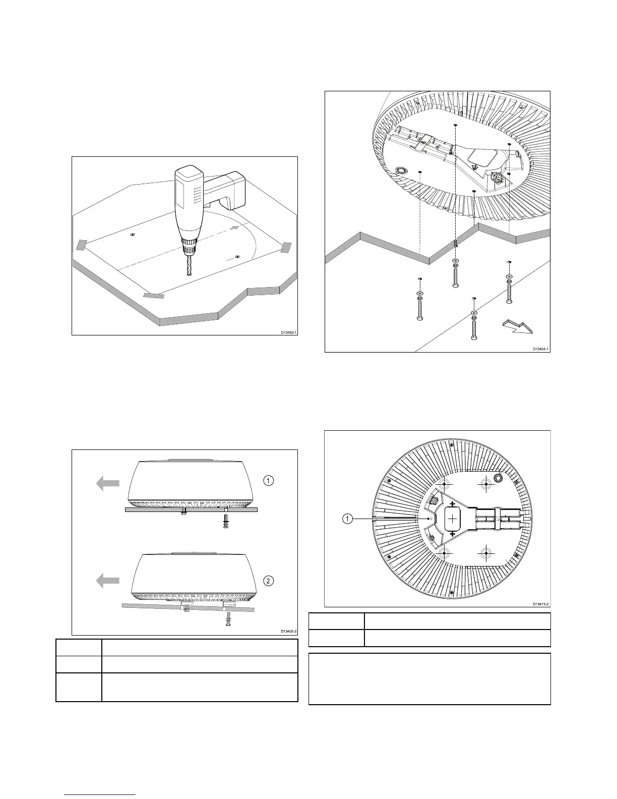
1.T apethetemplatetothemountingplatform,
ensuringthatthearrowonthetemplateispointed
towardsthefrontofthevessel.
2.Drill3mmpilotholesinthefourpositionsshown
onthetemplate.
3.Drilloutthepilotholesto10mmdiameter.
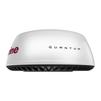
4.PlacetheQuantum™scannerinposition.Ifyou
arettingitonaplaningvessel,shimtherear
ofthescanner,sothatthebeampointsslightly
downintheforwarddirectionwhentheboatisat
rest,tocompensateforthebowrisingatcruising
speed
ItemDescription
1
Mountingplatform,non-planingboat(levelinstall)
2
Mountingplatform,planingboat(typicalplaning
angleshown)
5.Beforesecuringthescannertothemounting
platform,connectthepowercable(andoptionally
adatacable),ensuringthatallcablesarerouted
appropriately.Seethe4.2Connectionsoverview
sectionforfurtherinformationaboutmaking
connections,andcablerouting.
6.Ensuringthattheboltsdonotenterthescanner
basemorethan25mm(1inch),securethe
scannerwiththe4bolts,atwashersandspring
washersprovided,asillustrated.Ifnecessary,
useappropriateshimsorextrawasherstolimit
thelengthofboltenteringthescannerbase.
7.Tightentheboltstoatorqueof
15Nm(133lbf/inch).
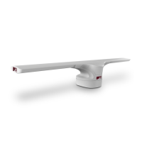
8.Attachasafetylanyard(notsupplied)toyour
vessel,andsecurethefreeendtothescanner
usingtheattachmentpointshowninthefollowing
illustration:
ItemDescription
1
Safetylanyardattachmentpoint.
Note:IfyouareinstallingtheRadarscannerona
sailingvessel,additionalprotectionfortheRadar
scannermayberequired.Referto5.2Radar
scannerprotection—sailingvessels.
30
QuantumRadome