SAM 400 SPEED-AREA-DISTANCE METER
13
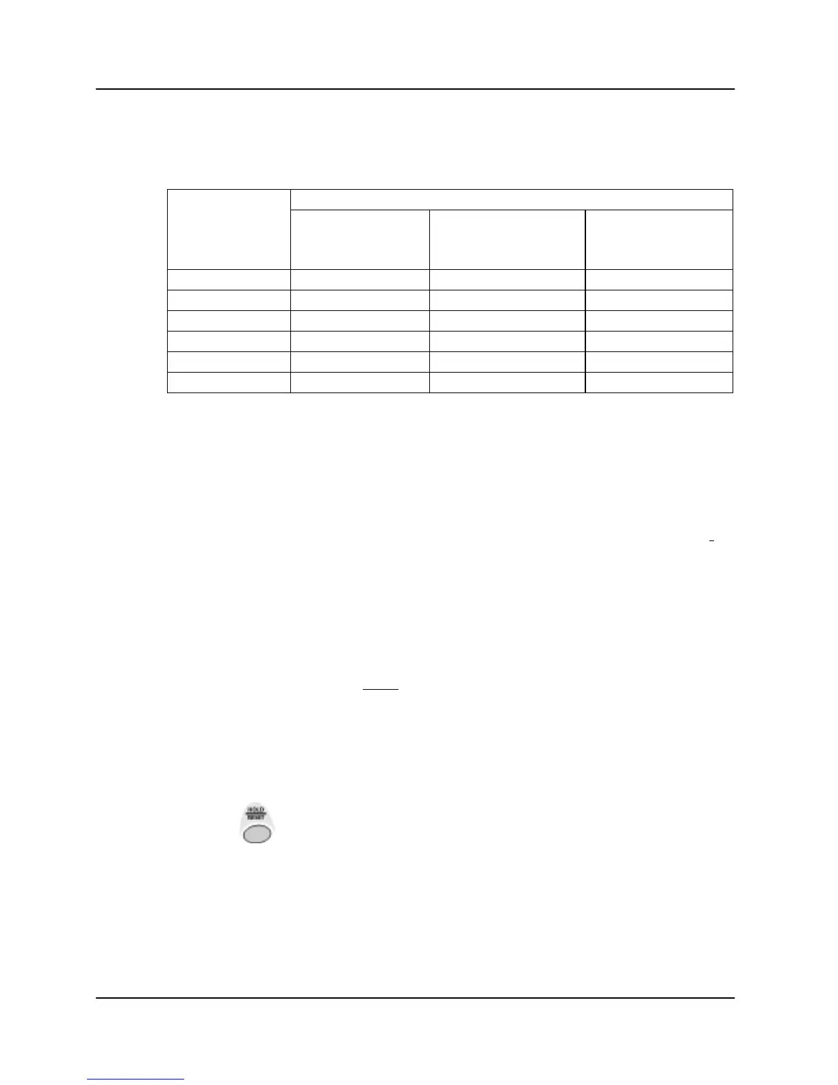
Number of Sensor magnets
The table gives the number of magnets required to enable a speed update of
approximately once per second or faster on the display.
Typical speed in normal operation:
Tyre diameter
up to 5mph
(8km/hr)
6 to 9 mph
(9 to 15 km/hr)
10mph
(16 km/hr)
or over
12" (0.3m) 1 1 1
24" (0.6m) 1 1 1
36" (0.9m) 2 2 1
48" (1.2m) 4 2 2
60" (1.5m) 4 4 2
72" (1.8m) 4 4 2
Example Calculation 1
The tractor is fitted with a single-magnet propshaft sensor. The measured
distance for 10 rotations of the propshaft is 17'-6".
1. Convert the distance to inches :- (17' x 12")+6" = 210"
2. Divide by 10 (magnet pulses) to give the calibration factor:- 210" / 10 = 21"
3. Programme the factor '021.0' as described overleaf.
Example Calculation 2
A vehicle with row crop wheels is fitted with 4 magnets. It is found to move
144 feet for 10 rotations of the sensed wheel.
Converting the distance to inches and dividing by 40 gives a calibration
factor of (144' x 12") / 40 =43.2".
Manually setting the Factor
1. Press and hold the CAL button while switching the instrument on.
2. Press the key to toggle the display to "SSF" .
3. Use the small left and right buttons to adjust the factor as required.