SAM 400 SPEED-AREA-DISTANCE METER
9
Calibration
The instrument has two calibration modes. In calibration mode 1 you can
view and change the Forward Speed Sensor Factor, Implement Width/Nozzle
spacing, No. of nozzles per section (if ACI installed), Units, and RPM Sensor
Factor.
In calibration mode 2 you can set the forward speed alarm thresholds.
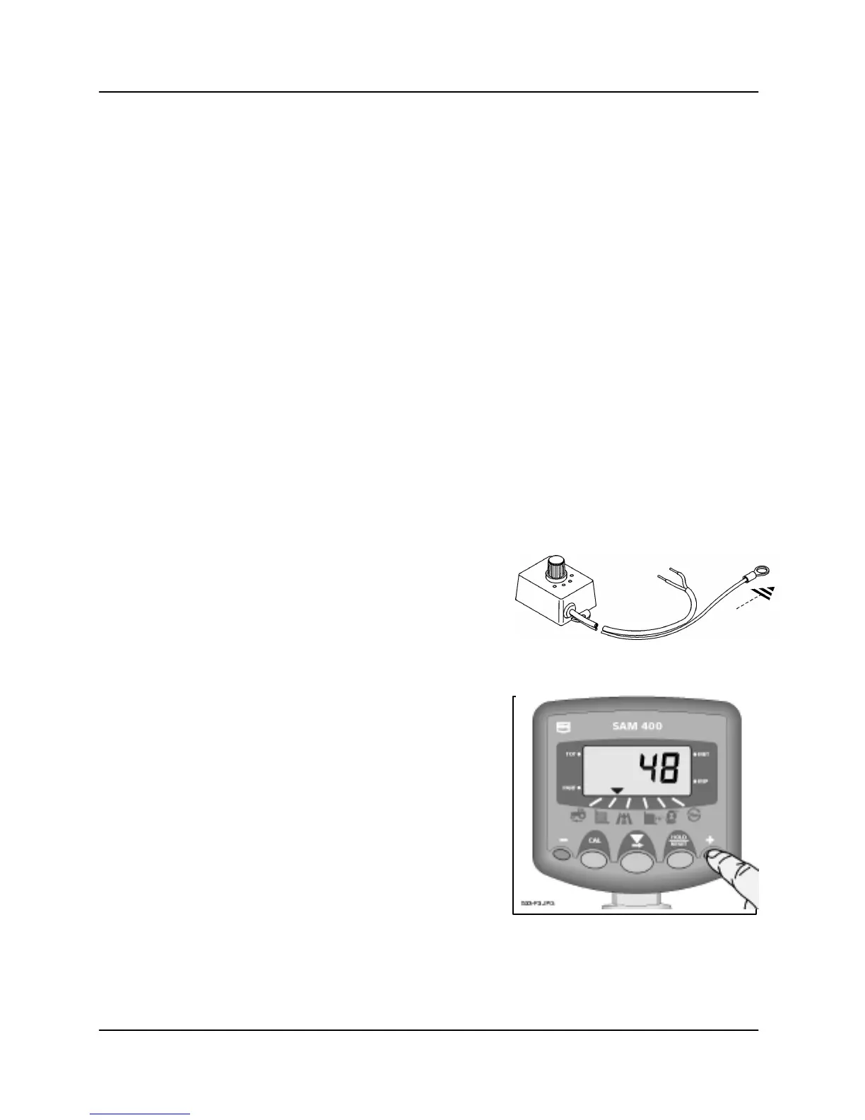
To allow entry to the CAL Modes, the Security Link Wire must be
connected to 0V.
View Working Width
Press and hold the right outermost
switch.
After a two-second delay, the display will
show one of the following,
(i) If a standard on-off override switch is fitted,
the display will show 'FuLL' when the
machine is in work and 'ZErO' when the
machine is out of work (or the hold button
is pressed).
(ii) If a Width Compensation Interface (WCI) is
fitted the display will show 'FuLL', '3/4',
'1/2', or '1/4' corresponding to the switch
position on the WCI.
(iii) If an Area Compensation Interface (ACI) is
fitted on a sprayer, the display will show
the number of nozzles for the boom
sections that are currently switched on.
E.g. An ACI is fitted on a 24 metre sprayer
with 5 boom sections. The nozzle spacing
is 0.5 metres and there are 10, 10, 8, 10,
and 10 nozzles respectively on each
section, giving 48 nozzles in total.
If the instrument has been programmed
with an implement width of 0.5 metres,
when all boom sections are on, the ACI
will signal the instrument that there are 48
nozzles in use, e.g. the display will show
48,
(48 x 0.5 m = 24 metre full width).