RTL87x2x Quick Start User Guide
Copyright 2023 Realtek Semiconductor Corporation.
All Rights Reserved. V
Figure List
Figure 2-1 EVB Wire Map .................................................................................................................................... 2
Figure 2-2 EVB board jumper connection ............................................................................................................ 2
Figure 2-3 Download images jumper connection ................................................................................................. 3
Figure 2-4 Connect GND........................................................................................................................................ 3
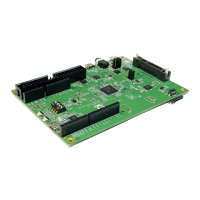
Figure 2-5 EVB Interface distribution ................................................................................................................... 4
Figure 2-6 EVB Power supply wiring .................................................................................................................. 4
Figure 2-7 MP Tool Startup Interface ................................................................................................................... 5
Figure 2-8 RTL87x2C Downloading Interface...................................................................................................... 6
Figure 2-9 Generate Flash map .............................................................................................................................. 8
Figure 2-10 MP Tool Startup Interface ................................................................................................................. 9
Figure 2-11 IC Type ............................................................................................................................................... 9
Figure 2-12 Flash Size .......................................................................................................................................... 10
Figure 2-13 OTA Header File Path ..................................................................................................................... 10
Figure 2-14 Generate OTA Header Files ............................................................................................................ 11
Figure 2-15 APP image ........................................................................................................................................ 12
Figure 2-16 Generate Config ................................................................................................................................ 12
Figure 2-17 Download steps ................................................................................................................................. 13
Figure 2-18 Detect Ready ..................................................................................................................................... 13
Figure 2-19 Open OK ........................................................................................................................................... 13
Figure 2-20 Open Failed ....................................................................................................................................... 13
Figure 2-21 J16&J17 Connection ......................................................................................................................... 14
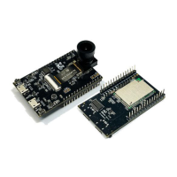
Figure 2-22 BEE4 EVB Uart Connection ........................................................................................................... 14
Figure 2-23 Normal power supply for sub-board .............................................................................................. 14
Figure 2-24 BEE4 EVB Power Supply............................................................................................................... 15
Figure 2-25 Download Success ............................................................................................................................ 15
Figure 2-26 Download Fail ................................................................................................................................... 15
Figure 2-27 EVB connection ................................................................................................................................ 16
Figure 2-28 Log wiring ......................................................................................................................................... 16
Figure 2-29 Print Logs steps ................................................................................................................................ 17
Figure 2-30 Print Logs successfully .................................................................................................................... 18
Figure 2-31 Bluetooth address setting ................................................................................................................. 19
Figure 2-32 Broadcast results on an IOS phone ............................................................................................... 19
Figure 2-33 Broadcast results on an Android phone ........................................................................................ 19
 Loading...