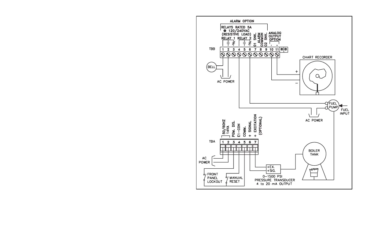
PRESSURE MONITORING EXAMPLE
An IMP indicator is installed as a monitoring device for pressure levels within
an industrial boiler. A pressure transducer with a range of 0-1500 PSI and a
corresponding 4 to 20 mA output is selected. The maximum allowable pressure
of the boiler is 1200 PSI, at which time a pressure relief valve will operate (this
makes the system inherently safe). In addition, when the relief valve trips, fuel
delivery to the boiler must be stopped. The relay option of the indicator is
employed to turn off the fuel at 1200 PSI. To provide for fail safe operation,
operator intervention is required to reset the latched relay in order to re-start the
boiler. The indicator’s other output is used to signal operators with a warning bell
when high pressures exist (1100 psi), so that they may take action to prevent
boiler shut-down. The alarm/setpoint values are set up for tracking, so changing
the cut-off alarm value changes the other alarm value an equal amount. The
indicator is programmed to provide a display of active alarms in both cases. Key
switches are installed in the panel to lock-out the front panel from operators and
to provide the means to reset the latched relay to re-start the boiler. The
linearizer/totalizer option is specified to integrate the average boiler pressure
over discrete time periods (ie. overnight, during peak use, start-up, etc). Peak
pressures are automatically stored with this option. Programming module #5
(Pro 5) is used to set up the integrator. The re-transmitted analog output is also
specified to drive a chart recorder with 4 to 20 mA for a hard copy of pressure
profiles for later evaluation.
Scaling of the indicator is done by programming module #1 (Pro 1). For dSP 1,
0 PSI is keyed-in. For INP 1, the transmitter is powered and connected to the
indicator and the boiler is at 0 PSI. The indicator then measures the output from
the transmitter. For dSP 2, 1000 PSI is keyed-in. Prior to INP 2, the boiler is fired
and brought to 1000 PSI as checked by a reference pressure gage. Once
stabilized, the indicator is allowed to measure the output of the transducer for
INP 2. Since there are no span/zero interactions, scaling is complete.
-23-