CURRENT LOOP INSTALLATION
WIRING CONNECTIONS
When wiring the 20 mA current loop, remove the bottom terminal block (TBA),
located on the rear of the unit. It is recommended that shielded (screened) cable be
used for serial communications. This unit meets the EMC specifications using
Alpha #2404 cable or equivalent. There are higher grades of shielded cable, such
as, four conductor twisted pair, that offer an even higher degree of noise immunity.
Refer to the numbers listed with the terminal descriptions below or those located on
the label. Install each wire in its proper location on the terminal block. When all
connections are made, replace the terminal block into its proper location.
SERIAL TERMINAL DESCRIPTIONS
8. PRINT REQ. - The Print Request terminal is pulled low to activate the unit to
transmit data according to the print function selected in Program Module #7
(Reference Programming Module #7 for more details). In order for a print
request function to occur, E1-CON (TBA #4) or E2-CON (TBA #8) pin must be
programmed for print request. Note: In order to guarantee a print-out, the
programmed E-CON pin must be held low for at least 20 msec. If this time
exceeds 800 msec, a second print-out may occur.
9. -20 mA SRC. - 20 mA current source return path for the transmit loop. Current
flows into this pin.
10. SI+ (Serial In+) -
11. SI- (Serial In-) -
The unit receives commands on the SI terminals. They are connected in series
with the transmit or output terminals of the device to be connected.
12. SO+/+20 mA SRC. (Serial Out+) - 20 mA current source for the transmit
loop (internally connected).
13. SO- (Serial Out-) -
The unit transmits the requested data on the SO terminals. They are connected
in series to the receive input of the device to be connected.
Note: The Serial Input terminals must be held in the mark condition (current
flowing) in order for the unit to respond to a Print Request terminal activation.
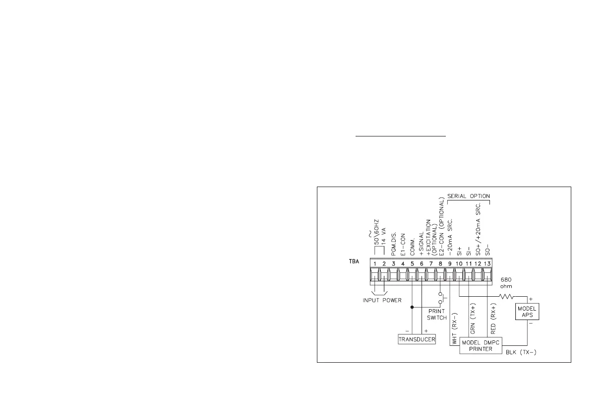
SERIAL COMMUNICATIONS EXAMPLES
CONNECTING TO AN RLC PRINTER
The drawing shows the indicator with the 20 mA Serial Communication
Option set-up with an RLC Model DMPC printer. An external current source is
required to implement the printer’s busy signal to the indicator’s receive loop,
which prevents overruns. The “Print switch” is a momentary contact, push
button type connected between the E2-CON (TBA #8) and the signal common
(TBA #5). The print function and E2-CON must be programmed, and the baud
rate must match those of the printer. If a printer is used which does not have a
‘busy’ line, current must still be flowing
into the indicator’s receive loop before
transmission can occur. A unit address of ‘0’ may be assigned in this case.
-34-