RED DSMC OPERATION GUIDE
COPYRIGHT © 2015 RED.COM, INC 955-0020_V6.0, REV-D | 163
SET UP STEREO/3D CONFIGURATION
This section describes basic procedures for connecting two (2) DSMC BRAINs in a Master/Slave configuration
for 3D operation.
NOTE: When providing the signals to a Stereo Image Processor (SiP) for verifying 3D alignment, set the HD-SDI
monitor output on both cameras to have the same overlay configuration.
NOTE: For genlock to function correctly, the cameras must be on the same firmware version, and must be using
the same project time base and recording frame rate.
To set up a Stereo/3D setup, follow the instructions below.
1. On both cameras, set the desired project time base and recording frame rate.
2. On both cameras, follow the instructions in “Sensor Sync” on page 159 to achieve Sensor Sync genlock
status.
The GEN and SYNC indicators in the Lower Status Row illuminate green.
3. Follow the instructions in “Set Up Master/Slave Operation” on page 160 to set Master and Slave camera
settings.
4. On both cameras, follow the instructions in “Set Reel Number, Camera ID, and Camera Position” on page
162 to prepare media and camera settings.
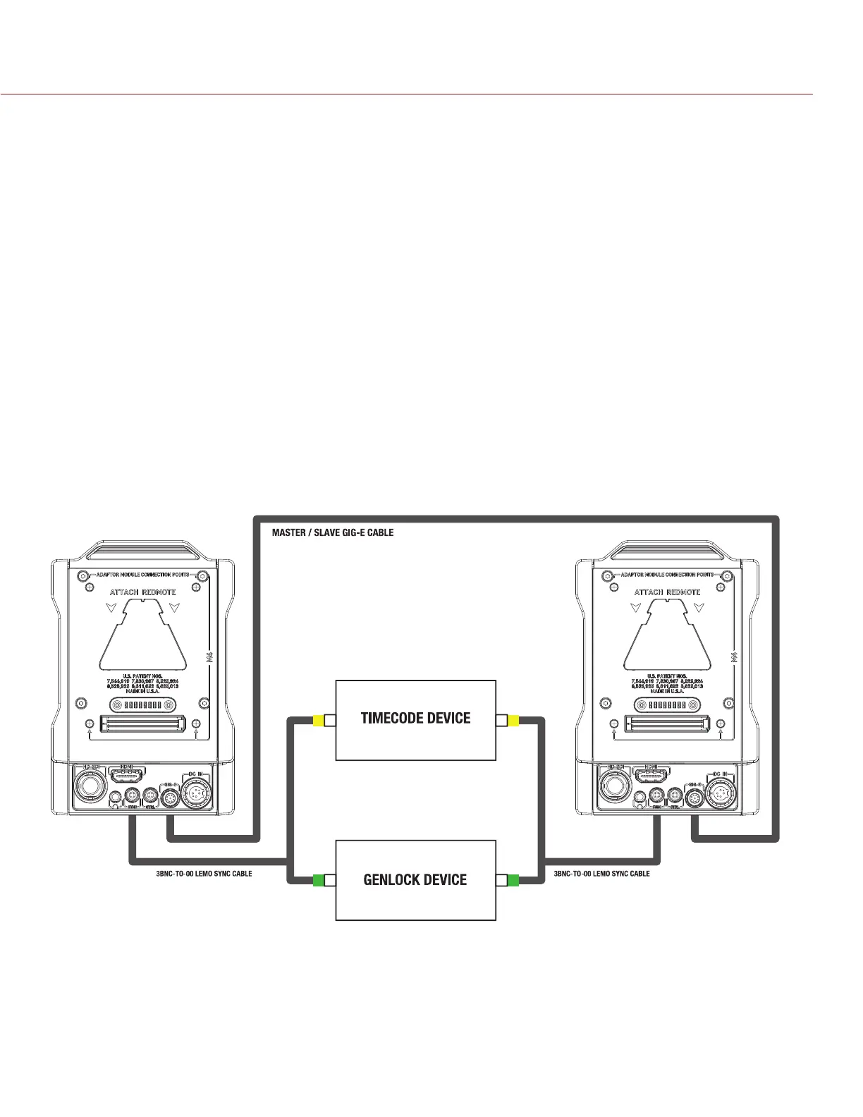
3D CONFIGURATION EXAMPLE
The diagram below is an example of how to set up a 3D configuration.
REQUIRED CABLES
790-0163: Master/Slave Gig-E Cable
790-0154: 3BNC-to-00 LEMO Sync Cable (required per camera)

 Loading...