Installation — Wiring | 29
POWER INPUT CABLE WIRING
Before you begin, purchase the correct cable size needed for your installation (refer to 'Power Input
Cable Sizing'(page27). Note: Poor quality cable can degrade over time when exposed to high
temperatures (such as in an engine bay). Make sure you purchase good-quality cable with a suitable
temperature rating for your installation.
For connector pinout information, see 'Power Cable Connector (A) Pinouts'(page48).
1. Make sure the Power Wiring Loom is disconnected from the Main Unit.
2. Place the Auxiliary Battery and TVMSRogue Main Unit in their final positions. Run the cables
and then trim or extend them as needed — refer to 'Joining/Extending Cables'(page28).
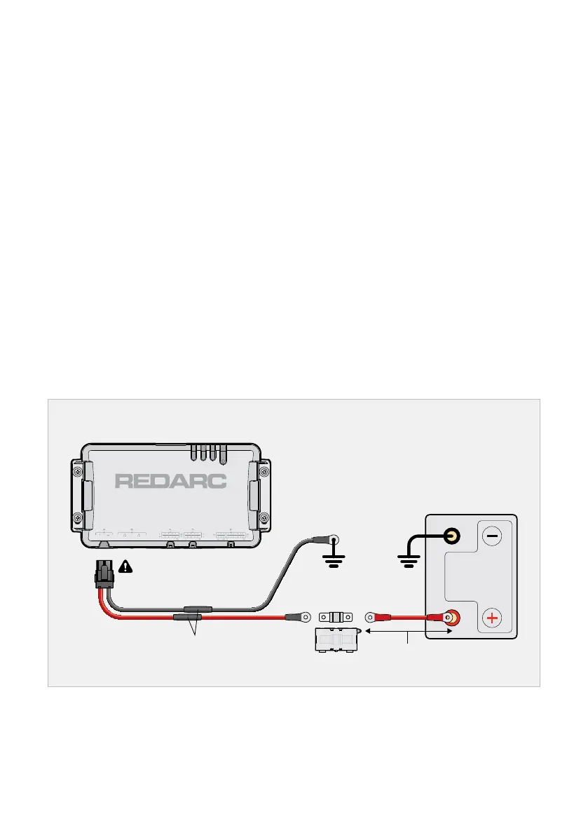
3. Connect the Red Cable (+) of the TVMSRogue Power Wiring Loom to the Auxiliary Battery
positive terminal. Fuse the Cable to 50 A (fuse not supplied). Position the Fuse as close to the
Auxiliary Battery as possible, ideally no more than 150 mm (6") away.
4. Connect the Black Cable of the Power Wiring Loom (negative/ground) to either of the following:
Ground (i.e. a vehicle chassis ground stud)
The GND (⏚) terminal of the Manager’s Battery Sensor (not supplied — refer to the instruction
manual supplied with the Manager)
When all other wiring of Outputs (C/D) and Inputs (E) is complete, plug the Power Wiring
Loom into the Power Input interface (A) on the Main Unit.
Power Wiring Loom Wiring
50 A Fuse
(and holder)
Extend cables as required
Auxiliary
Battery
Do not plug into Main Unit
until wiring of C,D and E is
complete
< 150 mm (6")
 Loading...