BlackMax – Installation and Operation Manual
Page 11 of 36
Issue date: 24/11/2023. Version 13.0
Step 4. Electrical Connections
Before any electrical connections are made, check all internal
electrical connections are secure and have not come loose during
transport.
Ensure that all breakers, as well as those supplying power to the
unit, are turned OFF.
4.1 Overview of the connection layout
To access the full 6kVA power of the BlackMax the load needs to be hard wired to terminals inside the unit, usually via an
external switchboard. The two power points are rated at 15A (3.6kW) and 10 amps (max. 2.4kW).
Earthing the Unit: The unit should be earthed to an appropriate earth stake. The earth cable can be connected to the earth bar
(or terminal block) inside the unit with the cable passed out through the second 25mm gland on the lower left side of the
BlackMax. Alternatively, the BlackMax can be earthed via an external switchboard with an Earth stake installed.
MEN Link: There is a MEN link installed in the BlackMax. If an external switchboard contains a MEN link, then the one inside the
BlackMax should be removed & the BlackMax hard wired to the main switchboard.
The generator should be hard-wired to the terminal block inside the unit. Alternatively, an AC coupled renewables sources or
the grid connection can be hard-wired to the same terminal block inside the unit. Please note, the BlackMax doesn't support the
concurrent operation of a generator and either the grid supply or an AC-coupled renewable energy source. The inverter needs
to be pre-configured for one of these options. By default, the BlackMax is set up for a generator. Therefore, please inform
RedEarth before connecting the system to an alternative renewable energy source. See section 4.5 AC Source Connection
below.
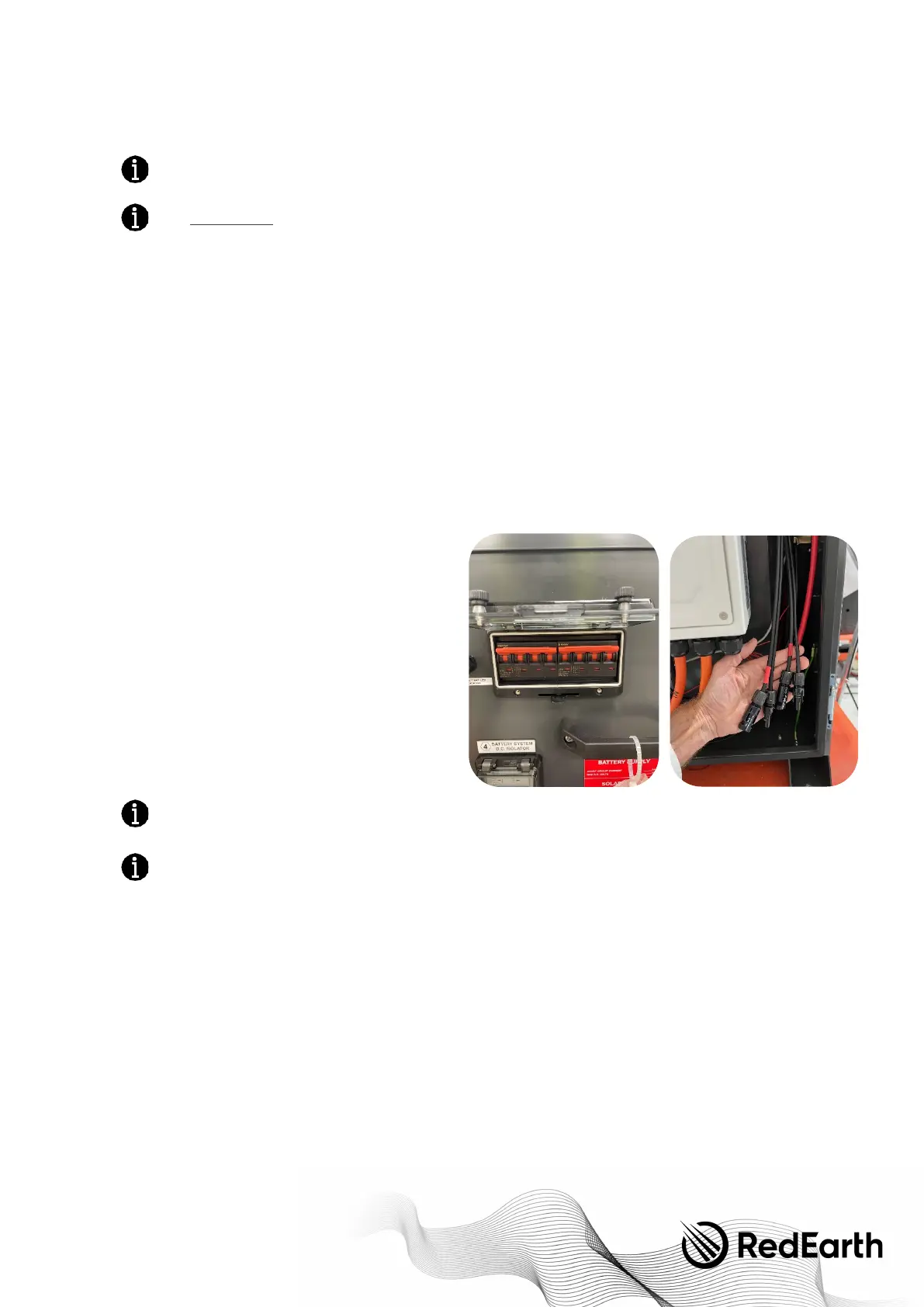
4.2 Solar array connection
For ease of installation, the BlackMax comes with its own PV
isolation MCBs and pre-terminated MC4 connectors on the
inside of the unit, as shown.
To c o n n e c t t h e s o l a r p o w e r , take the two cables coming from
each Solar array, insert the unterminated cables through the
hole on the right side of the system using a 25mm
weatherproof gland from the Parts kit. Then terminate the
correct MC4’s on the cables once it is inside the unit. Suitable
MC4 connectors are included in the Parts kit. Next, check for
correct polarity and Voc at the isolator terminals,
Then, with the BlackMax PV breaker still in the off position
connect the PV cables from the solar array to the pre-
terminated MC4 cables inside the unit. The PV array is now
ready to be used.
When exposed to light, photovoltaic (PV) array supplies D.C.
voltage to the Inverter.
Installing a PV array with voltage or current values above the
inverter rating will damage the BlackMax unit and will void the
warranty.
4.3 Battery connection
The RedEarth Troppo batteries are shipped inside the unit and can be found in the rear section of the BlackMax.
For transportation or maintenance or to add an additional Troppo battery, the batteries can be accessed from the top by lifting
the lid, or from the rear by removing the rear panel.