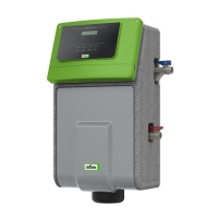
— English Vacuum spray degassing — 06.07.2016 - Rev. B
Risk of injury due to tipping over of the device
Risk of bruising or crushing caused by tipping over of the device
• Ensure sufficient stability of the device.
• Weigh down the bearing surface of the device's transport unit with suitable means.
Note!
The screw connections at the device may loosen when the device is moved to another location.
Prior to using the device check the screw connections for proper seating and sealing.
Note!
Avoid leaks at the connections.
When connecting the device to the facility system, ensure that the connections for degassing and make-up are not
twisted.
Proceed as follows:
• Connect the device at the return flow side of the plant system.
– In this manner, you ensure that the device is operated within the permissible pressure and temperature ranges.
• In the case of a plant system with return flow admixture or a hydraulic switching point, connect the device upstream of the
switching point.
– In this manner, you ensure the water degassing in the 'V' main volume flow at temperatures ≤ 70 °C.
– damage due to improper connection! Bear in mind that the device may be subject to additional stresses through the
connection of piping or hose connections to the plant system. Ensure that all connections to the plant system are free from stresses. If
necessary, provide support structures for the pipes.
– Property damage caused by leaks! Leaks in the connection pipes to the device can cause material damage to the plant
system. Use only connection pipes with appropriate resistance against the plant system temperature.
The device is pre-wired and must be adapted for the local system conditions.
Proceed as follows:
1. Complete the water side connections from the device to the plant system.
2. Complete the electric connection as shown in the terminal plan, see chapter 6.5 "Electrical connection" on page 25 .
Note!
During connection, ensure the operability of the valves and the inlet options for the connecting lines.

 Loading...