— English Vacuum spray degassing — 06.07.2016 - Rev. B
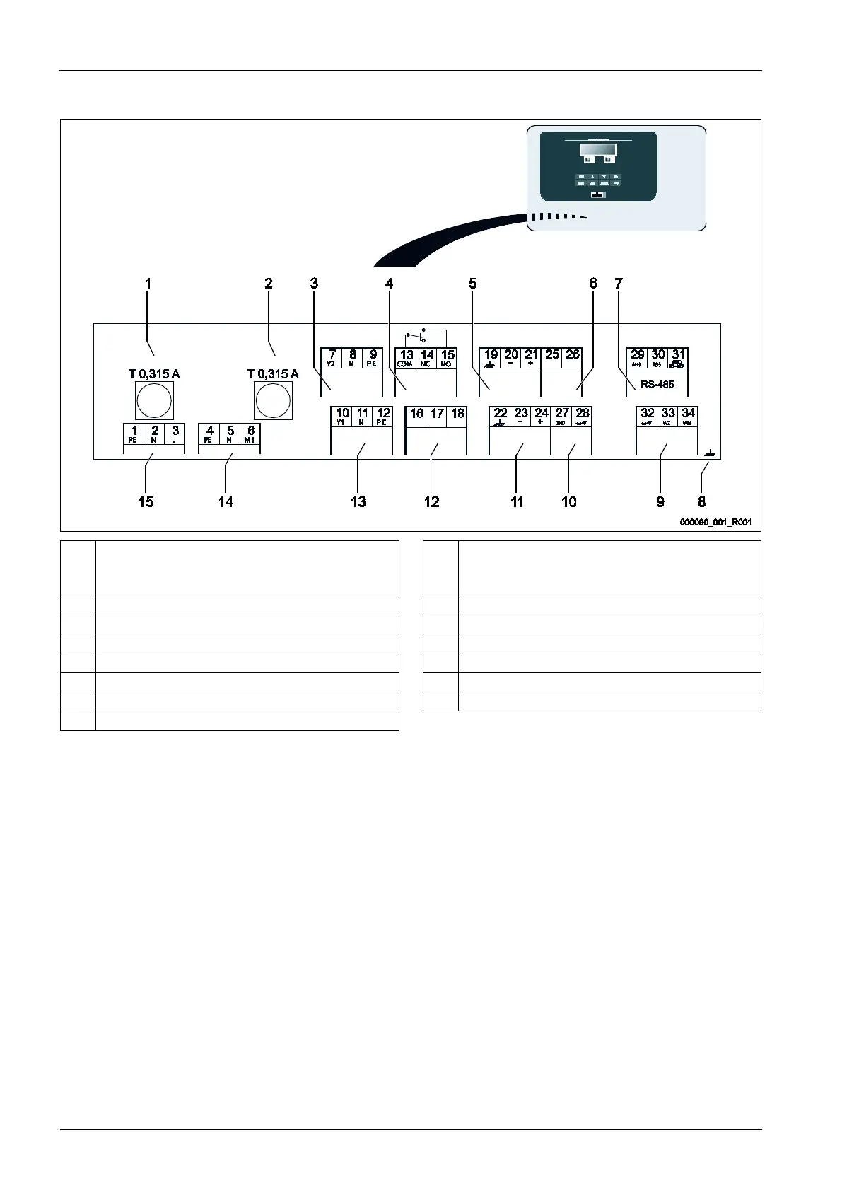
1 "L" fuse for electronics and solenoid valves 9 Digital inputs
• Water meter
• Insufficient water
2 "N" fuse for solenoid valves 10 "CD" 3-ways motor ball valve
3 Overflow valve (not for motor ball valve) 11 Pressure analogue input
4 Group message 12 External makeup demand (Levelcontrol only)
5 Optional for second pressure value 13 Makeup valve
6 "CD" 3-ways motor ball valve 14 Pump
7 RS 485 interface 15 Mains supply
8 Shielding