Vacuum spray degassing — 06.07.2016 - Rev. B English —
1 PE
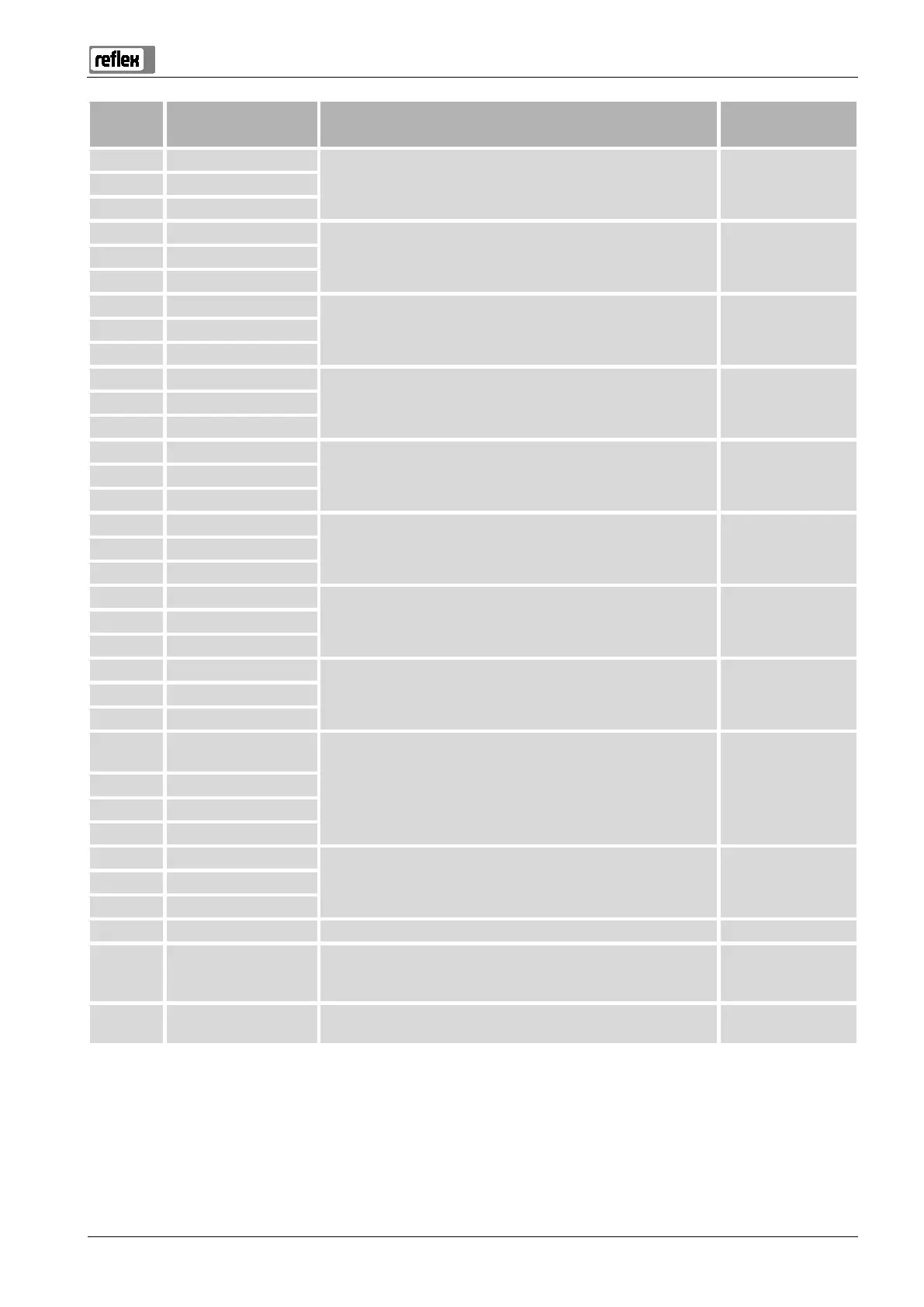
230 V power supply via mains cable and plug. Pre-wired 2 N
3 L
4 PE
"PU" vacuum pump for degassing. Pre-wired 5N N
6 M1 M 1
7 Y2
Overflow solenoid valve
Not used in standard model
--- 8 N
9 PE
10 Y 1
"CD" 3-
ways motor ball valve for regulating the degassing of makeup
and system water.
Pre-wired 11 N
12 PE
13 COM
Group message (floating). User, optional 14 NC
15 NO
16 Not assigned
External makeup demand from a pressurisation station; controller
must be set to "Levelcontrol"!
User, optional 17 Makeup (230 V)
18 Makeup (230 V)
19 PE shield
Level analogue input, not used by the device. --- 20 - Level (signal)
21 + Level (+ 18 V)
22 PE (shield)
Pressure analogue input for display and makeup; controller must be
set to "Magcontrol"!
Pre-wired 23 - Pressure (signal)
24 + Pressure (+ 18 V)
25 0 – 10 V (correcting
variable)
"CD" 3-ways motor ball valve, not used with the device. ---
26 0 – 10 V (feedback)
27 GND
28 + 24 V (supply)
29 A
RS-485 interface. User, optional 30 B
31 GND
32 + 24 V (supply) E1 Supply for E1 and E2. Pre-wired, bridged
33
E1 Contact water meter, for example in Fillset, see chapter 4.6 "Optional
equipment and accessories" on page 13 , for makeup evaluation,
contact 32/33 closed = meter pulse.
User, optional
34
E2 Insufficient water switch, not used with the device, contact 32/34
closed = OK.
Pre-wired, bridged