11
6.4 CONNECTING DRAIN LINE
For all evaporators, a drain line union is recommended
for ease of installation and future servicing and should be
located in close proximity to the drain pan.
EK, LM, LJ & DJ: A 7/8" ID removable drain coupling is
supplied with each unit.
EM & EJ are supplied with 1 1/4" FPT connections.
FOR ALL MODELS, connect the drain line as follows:
1. Replace the rubber gasket to prevent condensate
leakage.
2. Locate the union as close to the drain pan as possible.
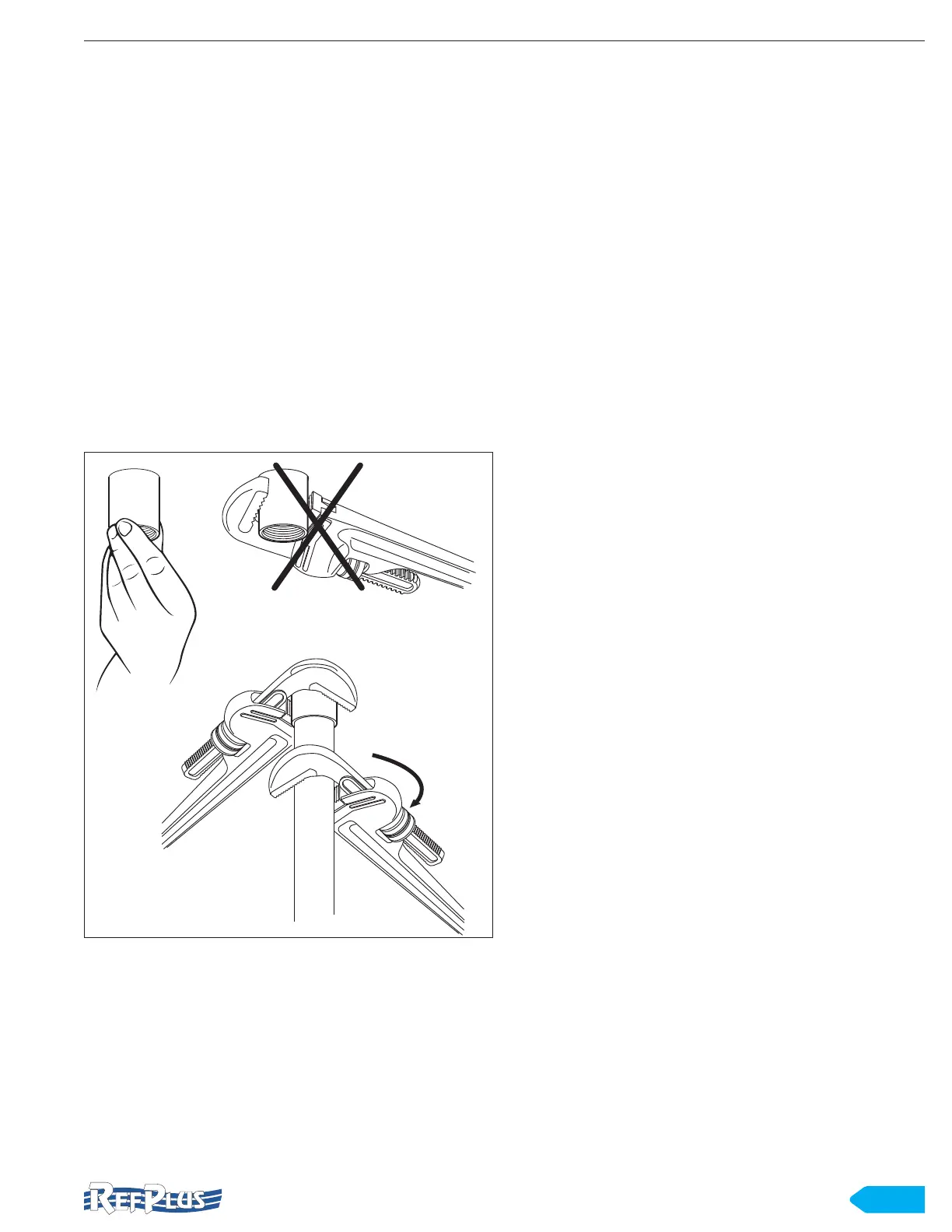
3. Hand tighten the coupling as shown in Figure 4. DO
NOT use wrench to tighten coupling in place as this
could damage the gasket and cause leaks. Once the
coupling is in place, connect the drain pipe and tighten
pipe using two wrenches as shown. The use of two
wrenches will prevent the coupling from twisting and
damaging the unit.
HAND TIGHTEN ONLY
LOCK COUPLING IN PLACE
WHILE TIGHTENING PIPE
Figure 4 Drain pan coupling
4. Sharply pitch the drain line and exit it through the
cooler with a short run.
5. Insulate and seal the drain line where it passes through
the wall.
6. Locate the drain traps in warm ambient air temperature
to prevent freeze-up.
Drain traps on low temperature units must be outside of
refrigerated enclosures. Properly protected from freezing,
copper or steel pipes should be used. Food approved plastic
can also be used for medium temperature coolers above
35°F (2°C). The drain line must have a minimum of 4’’ per foot
pitch for proper drainage. The unit must be perfectly level in
two directions. The drain line should be at least as large as
the evaporator drain connection. All plumbing connections
should be made in accordance with local plumbing codes.
All condensate drain lines must be trapped and run to an
open drain. They must never be connected directly to the
sewer system. Traps in the drain lines must be in a warm
ambiance.
We recommend a trap on each evaporator. Traps located
outside the building must be insulated and wrapped with a
drain line heater. When installing the heater, be sure to avoid
overlapping. The heater must be permanently energized. A
heat input of at least 20 W per linear foot of drain line for a
0°F (-18°C) room and 30 W per linear foot of drain line for
a -20°F (-29°C) room should be satisfactory. Always trap
drain lines individually to prevent vapour migration.
6.5 CONNECTING REFRIGERANT LINES
All refrigerant system components must be installed in
accordance with applicable local and national codes using
proper engineering practices. Refer to the piping diagrams
on page 36.
Use top quality refrigeration tubing that is internally free of
dirt, humidity or other contaminants. Unsealed tubing should
not be used. Long radius elbows are recommended.
Dry nitrogen must be swept through the lines while joints are
brazed to avoid oxidation and carbon deposits.
IMPORTANT: A calibrated pressure gauge and regulator
must always be used with nitrogen gas cylinders.
All external piping must be well supported. The unit will not
support external piping or valves.
If the condition arises where the suction line must be raised
to a point higher than the suction connection on the unit, a
suction line trap must be installed on the unit.
Horizontal suction lines should slope away from the
evaporator toward the compressor. Leak check and
evacuate the system using a two-stage deep vacuum pump.
Pull and hold for 24 hours a 500 micron vacuum.
INSTALLATION