12
6.6 CONNECTING THE EXPANSION VALVE
All units are supplied with a sweat expansion valve
connection. Expansion valves are eld supplied or may have
been installed at the factory (optional).
All units require the use of an externally equalized expansion
valve and are provided with a 1/4" OD equalizer line.
Check the operation of the expansion valve after the system
has reached the desired cooler temperature. If the coil is not
receiving enough refrigerant, reduce the superheat setting
on the expansion valve.
To ensure unit performance, the expansion valve must be
set at the proper superheat and at the lowest temperature in
which the system is expected to operate.
6.7 BULB LOCATION AND INSTALLATION
The location and installation of the bulb is extremely
important to the proper system performance and care
should be taken with its nal location. Accepted principles of
good suction line piping should be followed to provide a bulb
location that will give the best possible valve control.
The bulb should be securely fastened to a clean straight and
horizontal section of the suction line at the evaporator outlet.
This will ensure good thermal contact between the bulb and
the suction line for satisfactory expansion valve control. If
the bulb cannot be located in that manner, it may be located
on a descending vertical line only. The bulb should never
be located in a trap or downstream of a trap in the suction
line. Liquid refrigerant or mixture of liquid refrigerant and oil
boiling out of the trap will falsely inuence the temperature of
the bulb and result in poor valve control.
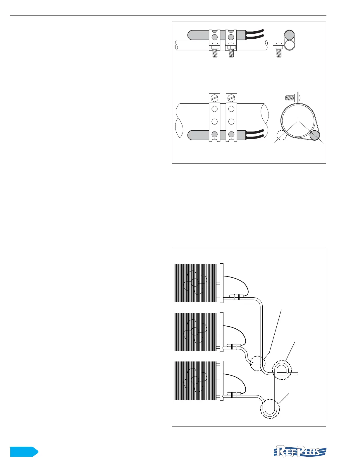
On suction lines 7/8” OD and larger, the surface temperature
may vary slightly around the circumference of the line. On
these lines, it is generally recommended that the bulb be
installed at 4 or 8 o’clock on the side of the horizontal line,
and parallel with respect to the direction of ow. On smaller
lines the bulb may be mounted at any point around the
circumference, however locating the bulb on the bottom of
the line is not recommended as an oil-refrigerant mixture
is generally present at that point. Figure 5 shows both
installation conguration. Certain conditions, specic to a
particular system, may require a different bulb location than
normally recommended. In these cases, the proper bulb
location may be determined by trial.
BULB ON SMALL SUCTION LINE
BULB ON LARGE SUCTION LINE
7/8” OD AND LARGER
8 o’clock 4 o’clock
Figure 5 Bulb installation
On multiple evaporator installations, the piping should
be arranged so that the ow from any valve cannot affect
the bulb of another, as shown in Figure 6. Approved piping
practices including the proper use of traps ensures individual
control for each valve without the inuence of refrigerant and
oil ow from other evaporators.
The vertical riser extending to the height of the evaporator
prevents refrigerant from draining by gravity into the
compressor during the off-cycle.
ABOVE AND BELOW MAIN SUCTION LINE
FLOW FROM UPPER VALVE
CANNOT AFFECT BULB
OF ANOTHER
INVERTED TRAP TO
AVOID OIL DRAINING
INTO IDLE
EVAPORATOR
FREE DRAINING
Figure 6 Bulb installation on multiple evaporator conguration
INSTALLATION