17
Setting Evaporator Pressure:
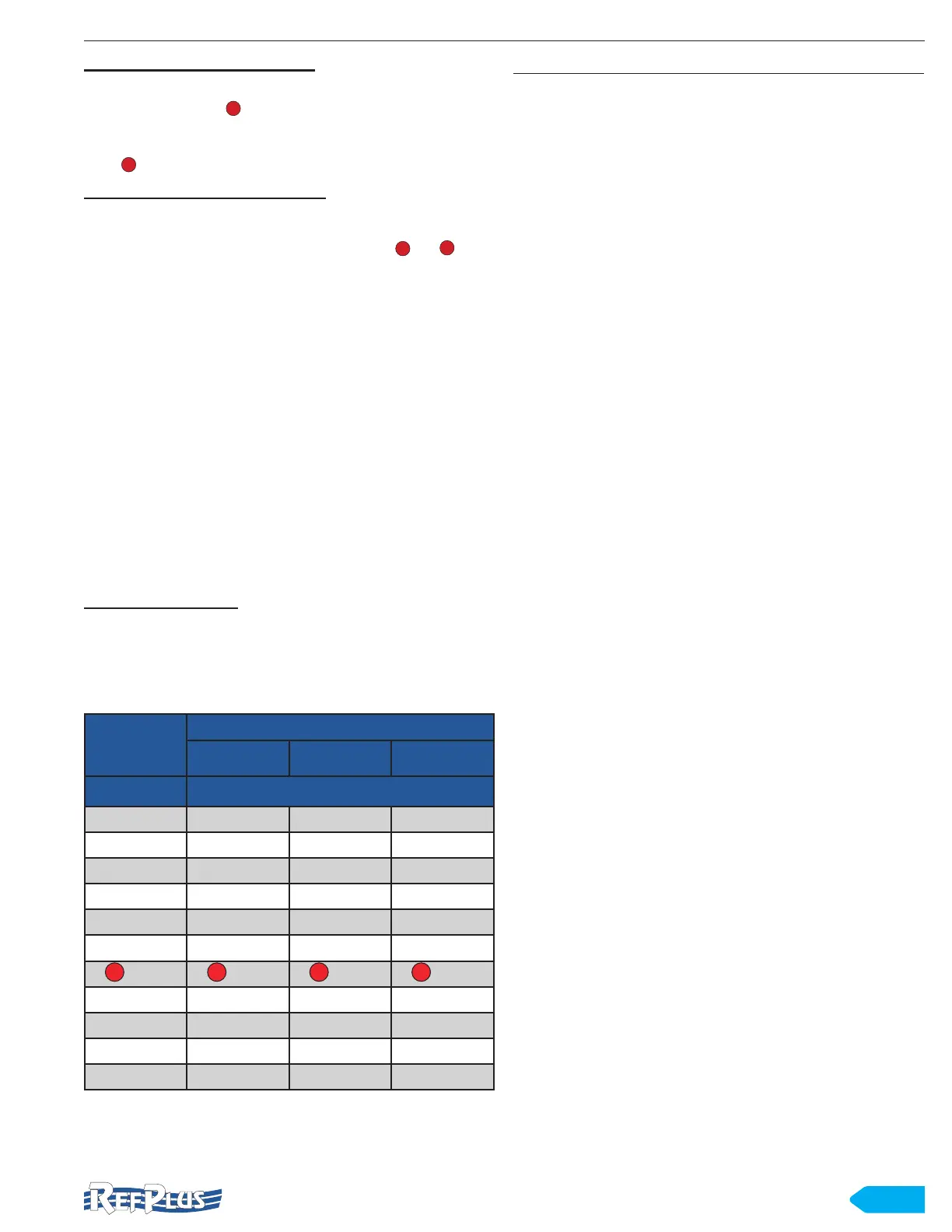
As an example, let say we want to achieve an average coil
temperature of 20
o
F ( in Table 3). Using a temperature-
pressure chart as reference such as the example in Table
3, now that we can begin by setting the Pressure to 51 psig
(item
).
Setting Evaporator Superheat:
In order to set the superheat, nd the Dew Point temperature
corresponding to the coil pressure. The evaporator coil
pressure and dew temperature are shown by and in the
chart below. To get superheat, compare the dew temperature
from the chart to the actual temperature of the evaporator
outlet piping. The difference in these two temperatures is
the superheat. In this example, when the pressure is 51
psig and the pipe temperature is 30 degrees, the superheat
will be 30 minus 25, or 5 degrees. As you continue to take
temperature readings, you can adjust the superheat and
pressure as needed until you’ve achieved the desired coil
temperature.
Note: In the absence of specic manufacturer recommendations,
a 4 to 6° F superheat for low temperature and 6 to 8° F for
medium temperature is recommended.
Note: When setting superheat in a system using a refrigerant
with glide, remember that pressure is constant throughout
the evaporator while the temperature will change during
boiling in the evaporator.
Adjusting for Glide:
When adjusting pressure and superheat, your goals are to
achieve the desired temperature, maximize coil efciency,
and protect the compressor for long service life. It all starts
by looking at the Pressure-Temperature (PT) chart included
with your refrigerant or any up-to-date refrigerants PT Chart.
PRESSURE
TEMPERATURE
AVERAGE BUBBLE DEW
(PSIG)
O
F
45 15 10 20
46 16 11 21
47 17 12 22
48 18 12 23
49 18 13 24
50 19 14 24
1
51
4
20
3
15
2
25
52 21 16 26
53 22 16 27
54 22 17 28
55 23 18 28
Table 3 Example of pressure-temperature chart
8. DEFROST SYSTEM
8.1 AIR DEFROST UNITS
Fan motors run continuously and a defrost time clock, or
low-pressure setting, stops the compressor when defrost is
required.
NOTE: The unit must not be in operation more than 16
hours per day.
8.2 ELECTRIC DEFROST UNITS
A time clock starts the defrost process by stopping the fan
and energizing the heaters. When the defrost thermostat
resets the time clock, it de-energizes the heaters and re-
starts the fan motors.
8.3 REVERSE-CYCLE HOT-GAS DEFROST UNITS
Reverse-cycle defrost systems introduce compressor
discharge gas through the suction line during defrost. The
amount of gas introduced is controlled by a solenoid bypass
valve and a gas defrost time clock.
Condensed refrigerant is relieved through a check valve.
The check valve bypasses the expansion valve leading to
the liquid line which has reduced pressure. The drain pan is
warmed by the entering hot gas to avoid freezing. Defrost is
initiated and terminated by the time clock.
NOTE: A minimum of 4 evaporators is required for an
efcient operation.
NOTE: The use of a suction to liquid heat exchanger is
recommended.
8.4 THREE-PIPE HOT-GAS DEFROST UNITS
During defrost, compressor discharge gas is introduced in
a separate hot gas line. The amount of gas introduced is
controlled by a solenoid bypass valve and a gas defrost time
clock.
To avoid excessive accumulation of liquid in the suction
accumulator, a heat exchanger is recommended. The drain
pan is warmed by the entering hot gas to avoid freezing. The
time clock cycles fan motors, liquid and hot gas solenoids.
NOTE: A minimum of 3 evaporators is required for an
efcient operation. Special engineering is required
for a 1 or 2 evaporator conguration. Please
contact RefPlus' Sales-Engineering department for
proper selection.
NOTE: A eld-installed pressure regulating valve may
be required on low temperature systems to control
compressor crankcase pressure.
4
1
1
2
DEFROST SYSTEM