13
6.8 SUCTION LINE CONSTRUCTION
RECOMMENDED VELOCITY FOR GOOD OIL RETURN OF POE WITH HFC - FPM (M/S)
FPM
Minimum
Horizontal
Minimum
Vertical
Design Maximum
Condensate NA NA ≤ 100 (0.5) 150 (0.8)
Liquid NA NA ≤ 300 (1.5) 300 (1.5)
Suction 500 (2.5) 900 (4.6) 1000 (5.1) - 3000 (15.2) 4000 (20.3)
Discharge 500 (2.5) 900 (4.6) 2000 (10.2) - 3000 (15.2) 3500 (17.8)
HG Defrost 500 (2.5) 900 (4.6) 1000 (5.1) - 2000 (10.2) 3000 (15.2)
Table 2 Recommended velocity for good oil return of POE with HFC - FPM (m/s)
INSTALLATION
IMPORTANT: A calibrated pressure gauge and regulator
must always be used with nitrogen cylinders.
The suction line must be sized to maintain proper line
velocities with a practical line pressure drop. It is usually
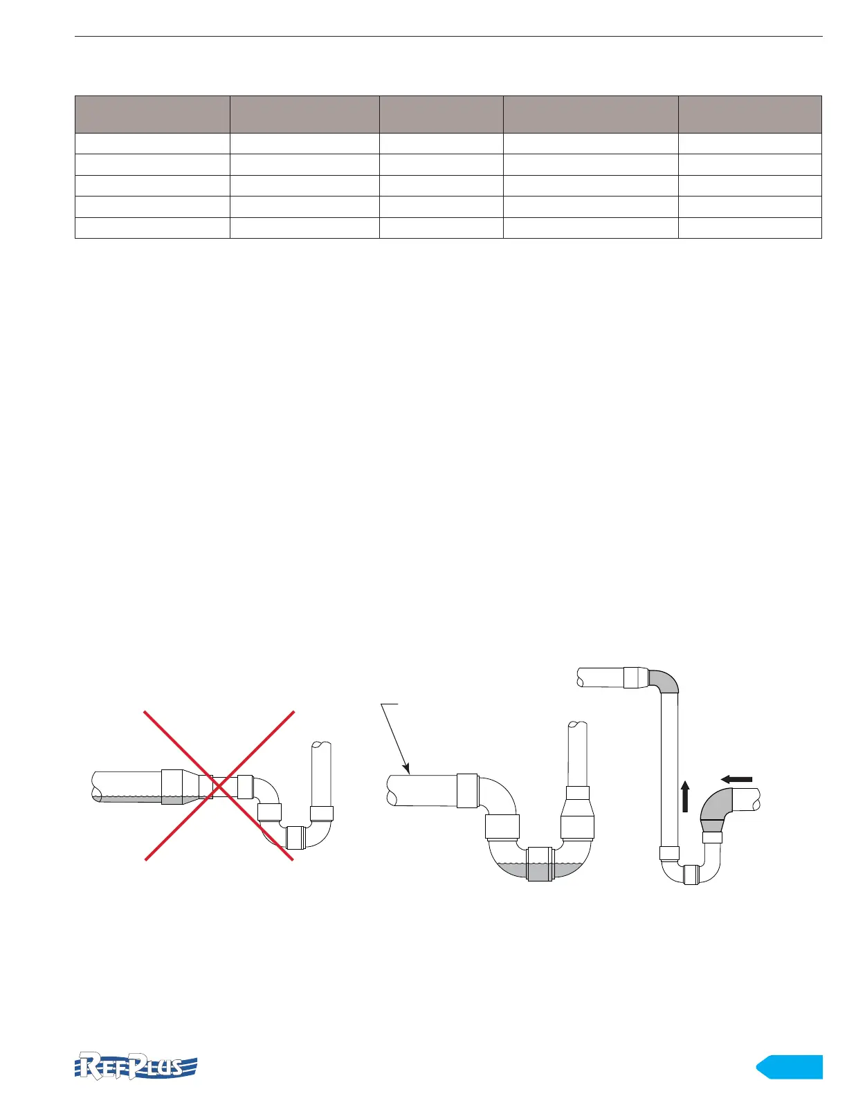
equal to 2°F (1.1°C). To ensure proper oil return, all horizontal
lines must be sloped down toward the compressor with a
minimum pitch of 1/4” (6.4 mm) per 10 ft (3 m).
An access tting must be installed (when not part of the
evaporator) on the evaporator suction line to read an
accurate suction pressure for superheat adjustment.
In situations where it is necessary for the suction line to rise,
an oil trap must be installed at the bottom of the riser as
shown in Figure 7, page 13. To ensure oil return through a
riser in the suction line, a velocity of no less than 1000 FPM
(5.1 m/s) is required. When a system has capacity variation
or unloaders, a double riser when at less than 50% capacity
may be necessary to keep the velocity at a minimum of 900
FPM (4.6 m/s). You can drop one size for suction riser to lift
the oil. A trap should be provided for each additional 20 ft
(6 m) of riser. See Figure 8.
Avoid oil and refrigerant migration between active and
inactive evaporators in a common suction system. When
multiple evaporators are connected to a common suction
line, it must enter from the top. The rst evaporator suction
connection should have an inverted trap as shown in Figure
9.
Suction lines should not be exposed to heat or the sun.
The line must be properly insulated if it is necessary to run
suction line outside of the building or through heated areas.
The suction line must be insulated in any situation where the
pipe may sweat or freeze.
If isolation valves are installed on the suction lines, full port
ball valves should be used.
OIL
OIL
SLOPE 1/4”
PER 10 FT.
TOWARD
COMPRESSOR
IMPROPER
PROPER PROPER
INSTALL REDUCERS
IN VERTICAL PIPE
INSTALL EXPANDER
IN HORIZONTAL PIPE
Figure 7 Suction oil trap construction