15
6.9 EXTERNAL EQUALIZER LOCATION
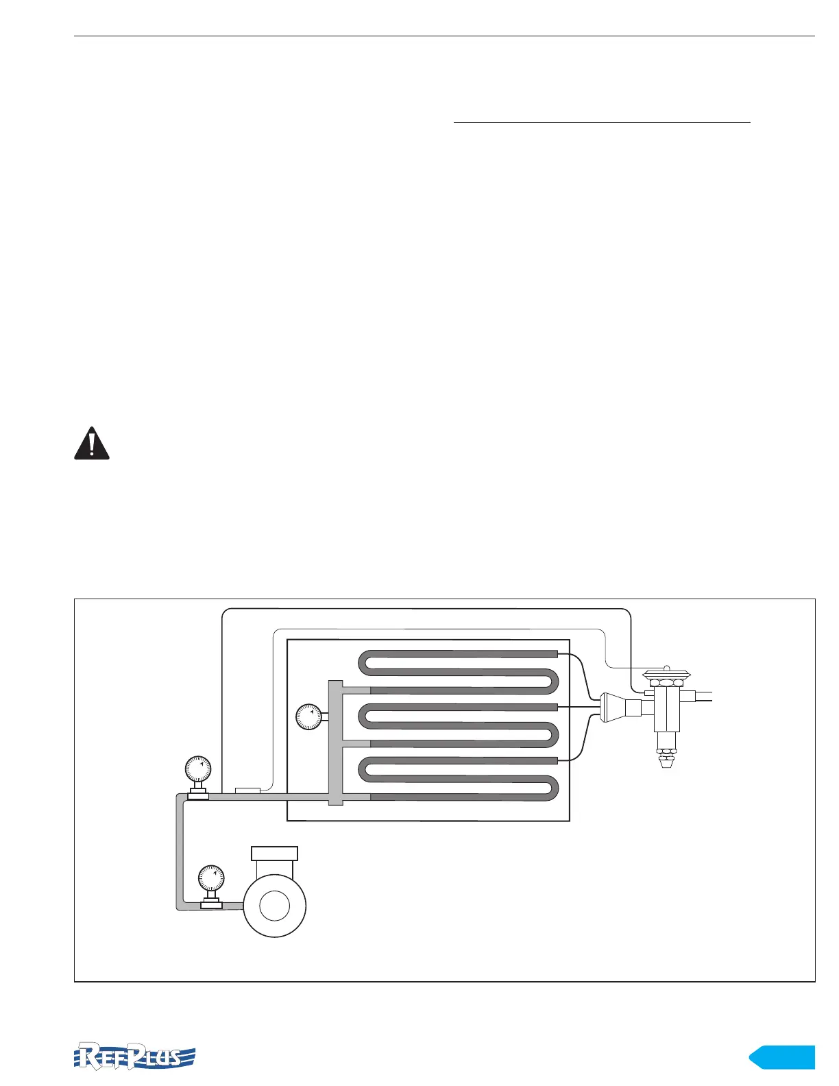
The purpose of the external equalizer is to sense the
pressure in the suction line at the bulb location and transmit
it to the TEV diaphragm. This usually means installing the
external equalizer immediately downstream from the bulb.
This ensures the correct pressure is signalled to the TEV.
In some situations this “ideal” location may not be possible.
In these cases, an alternate location, such as at B or C (see
Figure 10), could be used. However, the pressure at these
locations must be nearly identical to the pressure in the line
where the bulb is located.
In other words, locations B and C are acceptable as long
as these pressures are essentially the same as A when
the system is operating at full load. In the past, there has
been concern about installing the external equalizer “up-
stream” from the bulb. This was due to the possibility of
refrigerant leaking past the TEV push rods, passing through
the equalizer line and into the suction line, thus falsely
inuencing the TEV bulb temperature.
6.10 FIELD WIRING
WARNING: All system wiring must be done in
accordance with applicable codes and local
ordinances.
All internal wiring of fan motors, tubular heaters and
combination defrost termination fan delay control have been
factory connected. Before operating the unit, always double-
check all wiring connections, including the factory wired
terminals. Factory connections may vibrate loose during
transport.
Wiring diagrams are shown at the end of this manual for
reference only. Always refer to the wiring diagram supplied
with your specic unit.
When eld wiring the unit, consider the following:
• All wiring connections terminate on terminal block(s) in
the wiring compartment and are clearly labeled.
• The serial tag on the unit is identied with the electrical
characteristics for wiring the unit.
• Consult the wiring diagram in the unit for proper
connections.
• Wires should be copper conductor only and of the
proper size in order to handle the connected electrical
load.
• The unit must be grounded.
• For systems with multiple evaporator, the defrost
termination controls should be wired in series. Follow
the wiring diagrams for multiple evaporators carefully.
• Multiple evaporator systems should operate off of one
thermostat.
• If a remote defrost timer is used, the timer should be
located outside the refrigerated space.
INSTALLATION
B
A
C
EVAPORATOR
TEV
COMPRESSOR
Figure 10 Location of TEV external equalizer