REFU Elektronik GmbH REFUsol 40K / 46K-MV 55
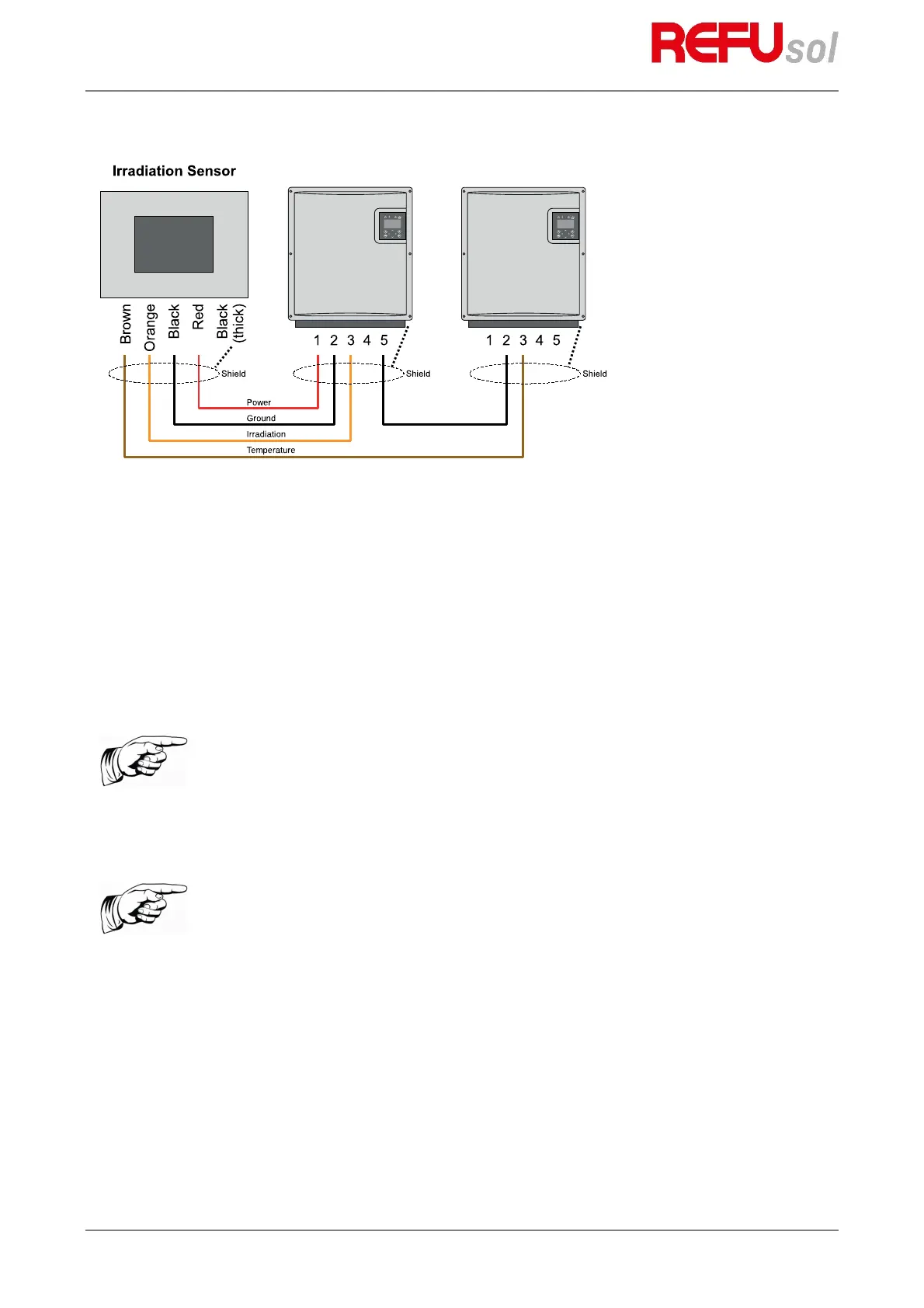
Fig. 23: Connection to two inverters (for AFCI variant)
In the AFCI variant, the irradiation and temperature sensor is connected individually to one inverter.
8.1.5
Configuration
The actual values of the sensor are shown on the display of the inverter at
Actual values > Sensor
.
The assignment of the sensor signals can be configures with PC software REFUset.
The data are recorded by the datalogger and are visible within REFUlog portal.
The actual values of the sensor can be viewed in
Actual values > Sensor
. The data continues to be recorded
with the data logger and can be viewed via REFUlog.
Pos: 78 /Inverter M anuals/Optionen /Externes A bschaltsign al/WR @ 1\mo d_14050778 48971_641.d ocx @ 7219 @ 2 3333 @ 1
Note:
The shield of the sensor line (dotted line) must be applied to PIN 2 and PIN 5!
The outer diameter of the connecting cable can be max. 8 mm.
Note:
If you do not use the temperature input, wire a jumper across PIN 4 and PIN 5.
Alternatively, you can also wire the jumper to the intermediate terminal point
(cable extension).