REFU Elektronik GmbH REFUsol 40K / 46K-MV 25
Fig. 8: Attaching with 3 screws
5. Tighten to torque of 2.5 Nm (1.8 ft lbs).
6. In order to avoid adhesive residue on the inverter, remove the display protection immediately after
installation.
Pos: 37 /Inverter M anuals/Insta llation/Gerät eanschlüsse/ 842 843 844 @ 3\ mod_1478 694943444_6 41.docx @ 25 392 @ 2 @ 1
4.7
Device Connectors
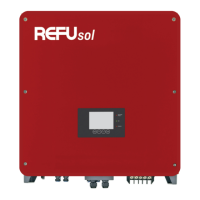
The following figure shows the DC switch and connectors of the inverter on its bottom side:
Fig. 9: Device connectors
The inverter is provided with the following connectors, as seen from left to right, top to bottom:
• Ethernet interface
• Sensor (irradiation, temperature or remote shutdown signal)
• RS485 connections (IN and OUT)
• Inverter earthing connection
• DC Connection for Solar Generator (DC+, DC-)
• AC Grid Connection (L1, L2, L3, N, PE)
Pos: 38 /Inverter M anuals/Insta llation/Erdu ng/842 843 8 44 @ 3\mod_ 147869499307 1_641.docx @ 2 5404 @ 2 @ 1