20
Chapter 8
BATTERY SWITCH MANAGEMENT
PANEL
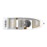
With the standard con guration there is an “on” and
“o type battery switch along with a 50 amp breaker
to protect the wiring running to the helm. Should an
electrical malfunction occur the breaker will “trip” to
safely interrupt current through the wiring circuit.
Always check for the cause of a breaker tripping before
resetting the device. e breaker above is in the normal
“on” position. Should it trip the yellow arm would end
up halfway to a full up position.
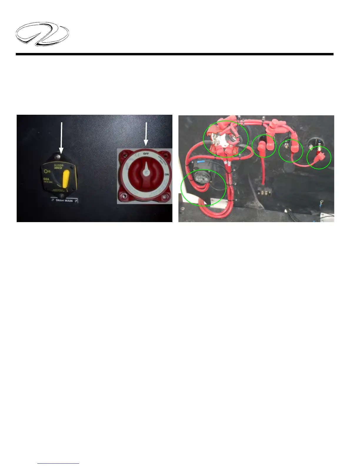
Periodically check all connections to the batteries, battery
switch terminals and to the breaker rear. Tighten as
needed.
Note that other breakers may accompany the dash
breaker depending on the vessel equipment onboard.
Electric head main breaker= 30 amps
Steering system breaker (outboard only)= 50 amps
STANDARD BATTERY
SWITCH
MAIN DASH BREAKER
50 AMPS
Note the photo above is a typical a view of the battery
switch management panel. With the battery(ies)
disconnected periodically check all nuts for tightness
under the red boots. Be sure to reinstall the boots to
prevent any arching possibilities.
TYPICAL BATTERY
SWITCH PANEL-REAR VIEW
SINGLE BATTERY SWITCH SYSTEM
 Loading...