Renesas RA Family EK-RA4E2 v1 – User's Manual
R20UT5175EG0300 Rev. 3.00 Page 6 of 30
Feb.27.23
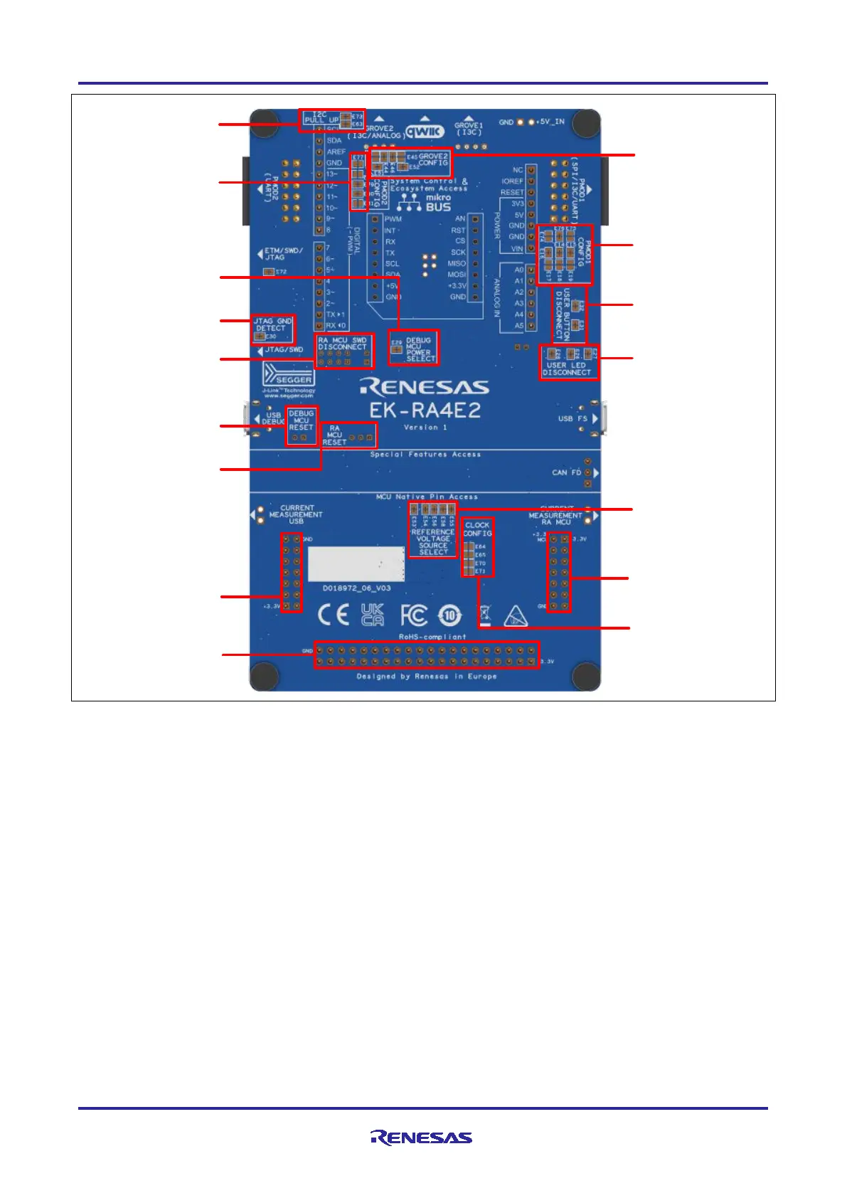
Breakout Pin
Header J1
Breakout Pin
Header J3
User LED
Disconnects
User Button
Disconnects
JTAG GND Detect
Disconnect
Breakout Pin
Header J2
RA MCU SWD
Disconnect
Pmod 1
Configuration
Reference Voltage
Source Select
I
2
C Pull-up
Disconnects
RA MCU
Clock Configuration
Pmod 2
Configuration
Grove 2
Configuration
Debug MCU Power
Select
Debug MCU Reset
RA MCU SWD
Disconnect
Figure 2. EK-RA4E2 Board Bottom Side
1.1 Assumptions and Advisory Notes
1. It is assumed that the user has a basic understanding of microcontrollers and embedded systems
hardware.
2. It is recommended that the user refers to the EK-RA4E2 Quick Start Guide to get acquainted with the kit
and the Quick Start example project that EK-RA4E2 board comes pre-programmed with.
3. Flexible Software Package (FSP) and Integrated Development Environment (IDE) such as e
2
studio are
required to develop embedded applications on EK-RA4E2 kit.
4. Instructions to download and install software, import example projects, build them and program the
EK-RA4E2 board are provided in the quick start guide.
5. The MCU fitted to the EK board may not contain the latest version of the on-chip boot firmware.