Renesas RA Family EK-RA4E2 v1 – User's Manual
R20UT5175EG0300 Rev. 3.00 Page 16 of 30
Feb.27.23
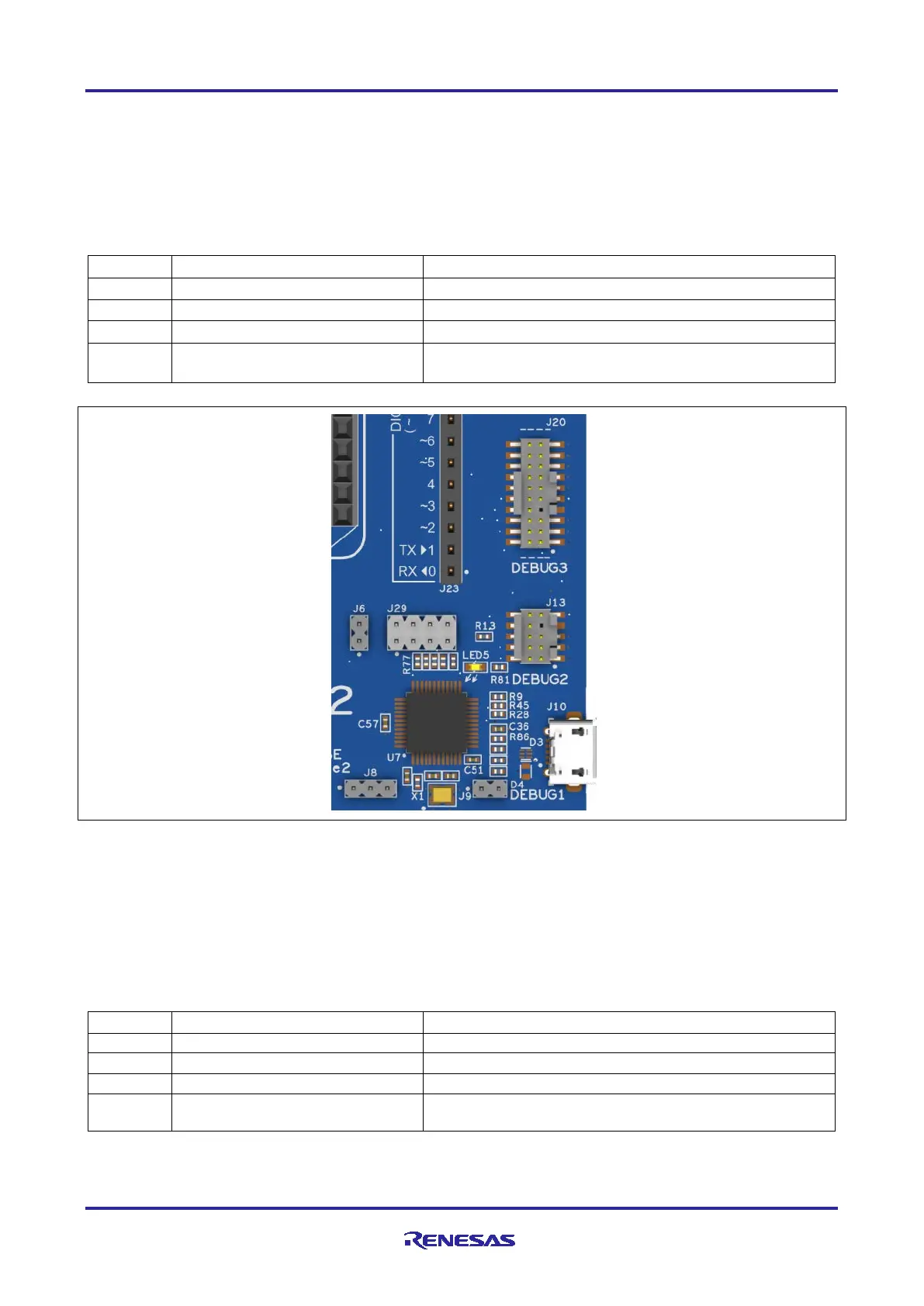
A yellow indicator, LED5, shows the visual status of the debug interface. When the EK-RA4E2 board is
powered on, and LED5 is blinking, it indicates that the RA4M2 debug MCU is not connected to a
programming host. When LED5 is on solid, it indicates that the RA4M2 debug MCU is connected to a
programming interface.
To configure the EK-RA4E2 board to use the Debug On-Board mode, configure the jumpers using the
following table.
Table 6. Debug On-Board Jumper Configuration
Target RA MCU MD connected to debug
Target RA MCU RESET# connected to nRESET signal
RA4M2 debug MCU in normal operation mode
Jumpers on pins 1-2, 3-4, 5-6, 7-8
Target RA MCU debug signals connected to the debug
interface
Figure 10. EK-RA4E2 Debug Interface
5.2.2 Debug In
One 20-pin Cortex
®
Debug Connector at J20 supports JTAG and SWD debug. One 10-pin Cortex
®
Debug
Connector at J13 supports JTAG and SWD. Either of these connectors may be used for external debug of
the target RA MCU.
To configure the EK-RA4E2 board to use the Debug In mode, configure the jumpers using the following
table.
Table 7. Debug In Mode Jumper Configuration
Target RA MCU MD connected to debug
Target RA MCU RESET# connected to nRESET signal
RA4M2 debug MCU is held in RESET
Jumpers on pins 1-2, 3-4, 5-6, 7-8
Target RA MCU debug signals connected to the debug
interface