Renesas RA Family EK-RA4E2 v1 – User's Manual
R20UT5175EG0300 Rev. 3.00 Page 20 of 30
Feb.27.23
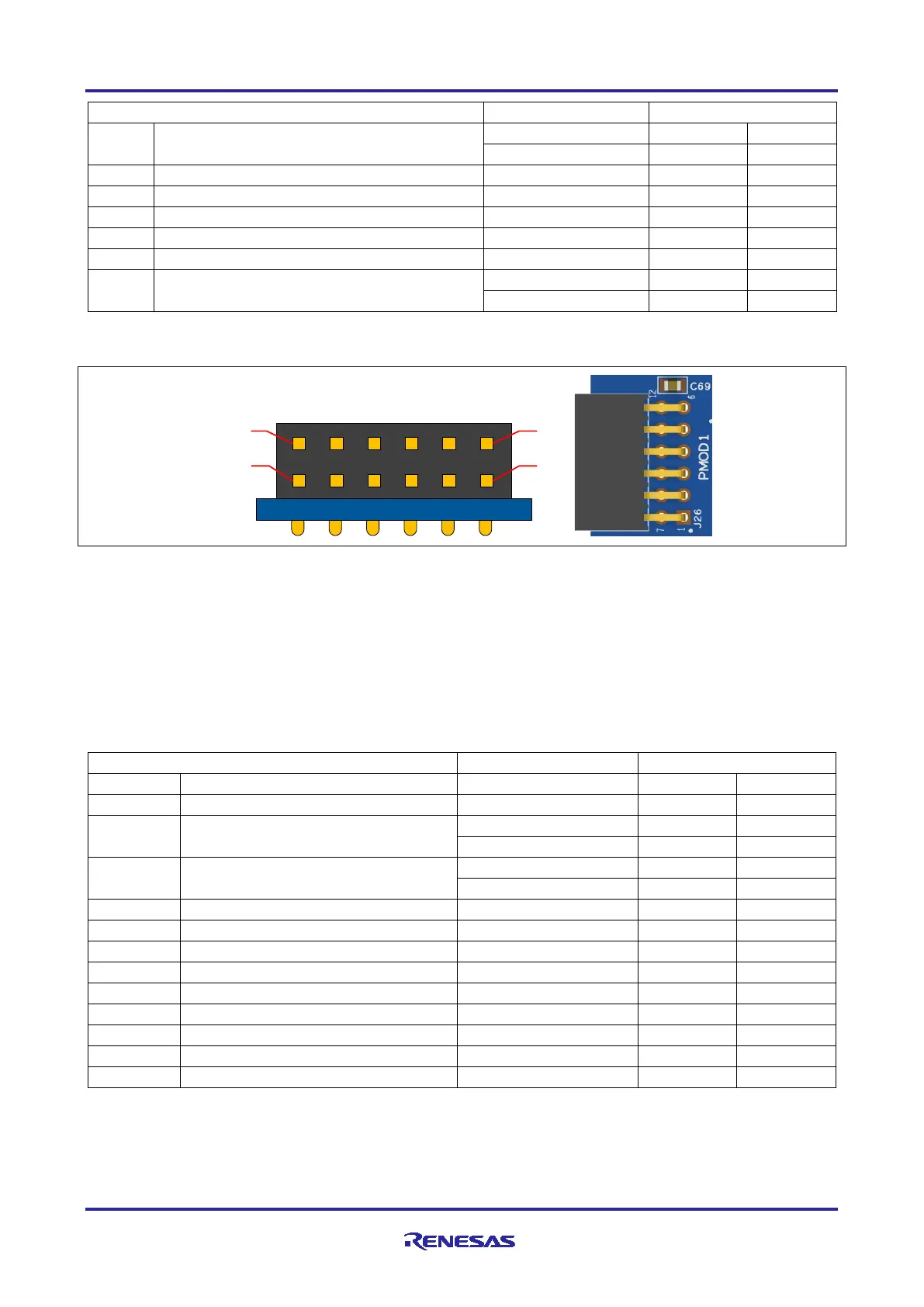
GPIO / INT (slave to master)
GPIO / RESET (master to slave)
Note: Exercise caution while modifying power source trace jumpers, E16 and E17. Permanent
damage to the EK-RA4E2 board and/or connected modules may result.
Figure 12. Pmod 1 Connector
5.3.3.2 Pmod 2
A 12-pin Pmod connector is provided at J25, Pmod 2. This Pmod is dedicated type-3A (expanded UART).
There are two options for SCI0 on Pmod 2. By cutting trace-cut links E79 and E80, and connecting solder-
bridge links E77 and E78, the secondary option is selected. The secondary option can only be used if the
main 20 MHz clock crystal is not being used. This also requires that trace-cut links E68 and E69 are cut, and
solder-bridge links E70 and E71 are connected. The benefit of using P212 and P213 over P410 and P411 is
that the serial data exchanged with Pmod 2 is not also shared with the debugger serial console.
Table 15. Pmod 2 Connector
GPIO / INT (slave to master)
GPIO / RESET (master to slave)
*Note: The use of these options also requires the disconnection of 20 MHz crystal Y1 (open links E68 and
E69) and the shorting of links E70 and E71.