Renesas RA Family EK-RA4E2 v1 – User's Manual
R20UT5175EG0300 Rev. 3.00 Page 10 of 30
Feb.27.23
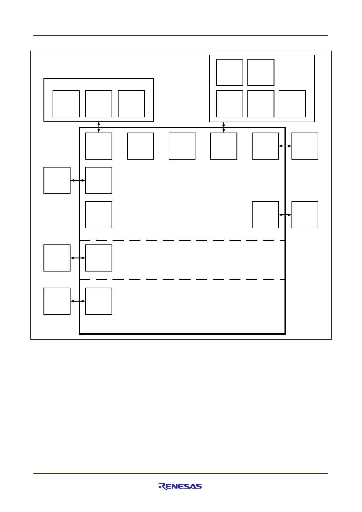
4.2 System Block Diagram
LEDs
Grove x2 Qwiic
mikroBUS
Arduino
Uno
Pmod x2PowerStatus
User
Programmable
GPIO
Power
Delivery
I
2
C/I3C
SPI/
UART/
I
2
C/I3C
Debug
I/F
Analog /
IRQ / IO
Reset
Switch
USB FS
CAN FD
Bus
Power
Meas.
Jumpers
CAN FD
User
Buttons
USB
Device
J-Link OB +
Debug + 10
pin and 20
pin
Voltage /
Current
Probes
EK-RA4E2 MCU
Board
System Control and
Ecosystem Access
Special Features
Access
Native Pin
Access
Figure 5. EK-RA4E2 Board Block Diagram
4.3 Jumper Settings
Two types of jumpers are provided on the EK-RA4E2 board.
1. Copper jumpers (trace-cut type and solder bridge type)
2. Traditional pin header jumpers
The following sections describe each type and their default configuration.
4.3.1 Copper Jumpers
Copper jumpers are of two types, designated trace-cut and solder-bridge.
A trace-cut jumper is provided with a narrow copper trace connecting its pads. The silk screen overlay
printing around a trace-cut jumper is a solid box. To isolate the pads, cut the trace between pads adjacent to
each pad, then remove the connecting copper foil either mechanically or with the assistance of heat. Once
the etched copper trace is removed, the trace-cut jumper is turned into a solder-bridge jumper for any later
changes.