EasyManua.ls Logo

Renesas EK-RA4E2

Renesas EK-RA4E2
36 pages
To Next Page IconTo Next Page
To Previous Page IconTo Previous Page
Loading...
Renesas RA Family EK-RA4E2 v1 User's Manual
R20UT5175EG0300 Rev. 3.00 Page 22 of 30
Feb.27.23
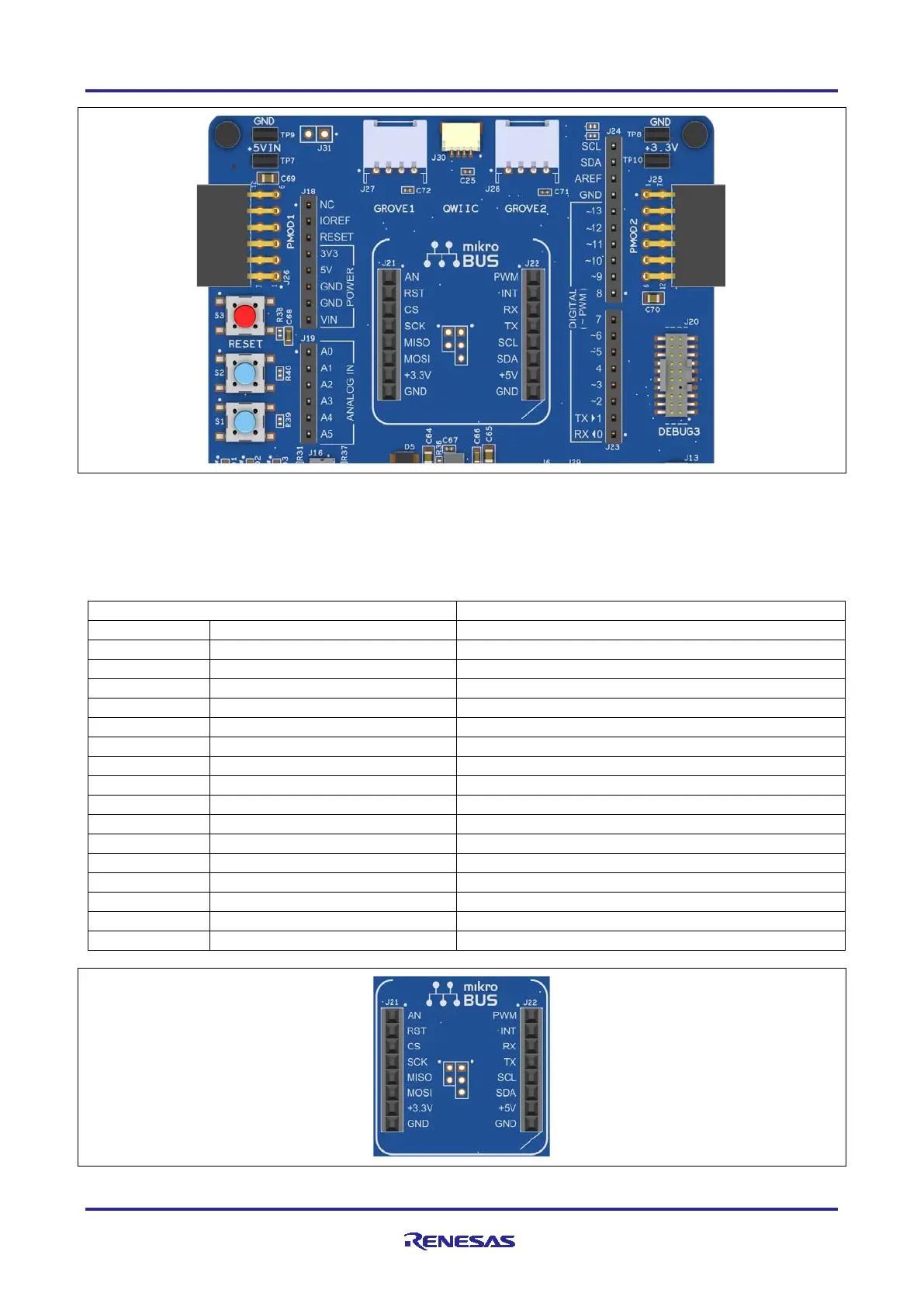
Figure 14. Arduino Uno Connectors
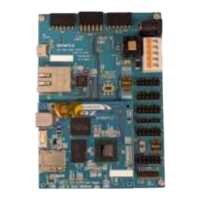
5.3.5 MikroElektronikamikroBUS Connector
In the center of the System Control and Ecosystem Access area is a mikroBUS compatible connector
interface. This interface is compliant with mikroBUS Standard Specifications revision 2.00.
Table 17. mikroBUS Connections
mikroBUS Connector
EK-RA4E2
Pin
Description
Signal/Bus
J21-1
AN (Analog)
P000 (AN000)
J21-2
RST (Reset)
P408
J21-3
CS (SPI Chip Select)
P301 (SSLA0)
J21-4
SCK (SPI Clock)
P111 (RSPCKA)
J21-5
MISO
P110 (MISOA)
J21-6
MOSI
P109 (MOSIA)
J21-7
+3.3 V
+3.3V
J21-8
GND
GND
J22-1
PWM
P403 (GTIOC3A)
J22-2
INT (Hardware Interrupt)
P105 (IRQ0)
J22-3
RX (UART Receive)
P410 (RXD0)
J22-4
TX (UART Transmit)
P411 (TXD0)
J22-5
SCL (I3C Clock)
P100 (SCL)
J22-6
SDA (I3C Data)
P101 (SDA)
J22-7
+5 V
+5V
J22-8
GND
GND
Figure 15. mikroBUS Connection

Table of Contents

Related product manuals