Renesas RA Family EK-RA4E2 v1 – User's Manual
R20UT5175EG0300 Rev. 3.00 Page 17 of 30
Feb.27.23
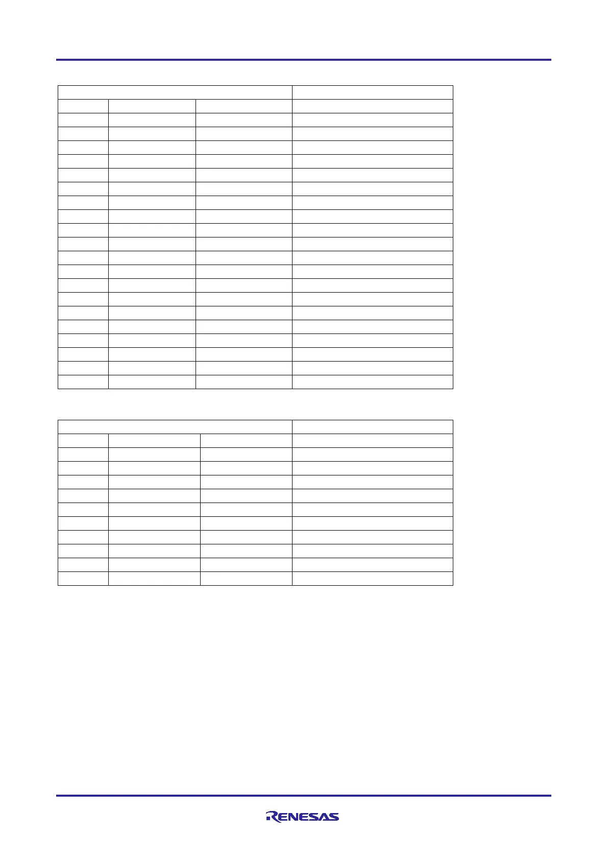
Table 8. JTAG/SWD Connector (J20)
Table 9. JTAG/SWD Connector (J13)
Note: The Cortex
®
Debug Connector is fully described in the Arm
®
CoreSight
™
Architecture Specification.
5.2.3 Debug Out
The EK-RA4E2 board can be configured to use the RA4M2 debug MCU to debug target RA MCU on an
external board.
A yellow indicator, LED5, shows the visual status of the debug interface. When the EK-RA4E2 board is
powered on, and LED5 is blinking, this indicates that the RA4M2 debug MCU is not connected to a
programming host. When LED5 is on solid, this indicates that the RA4M2 debug MCU is connected to a
programming interface.
To configure the EK-RA4E2 board to use the Debug Out mode, configure the jumpers according to the
following table.