Renesas RA Family EK-RA4E2 v1 – User's Manual
R20UT5175EG0300 Rev. 3.00 Page 25 of 30
Feb.27.23
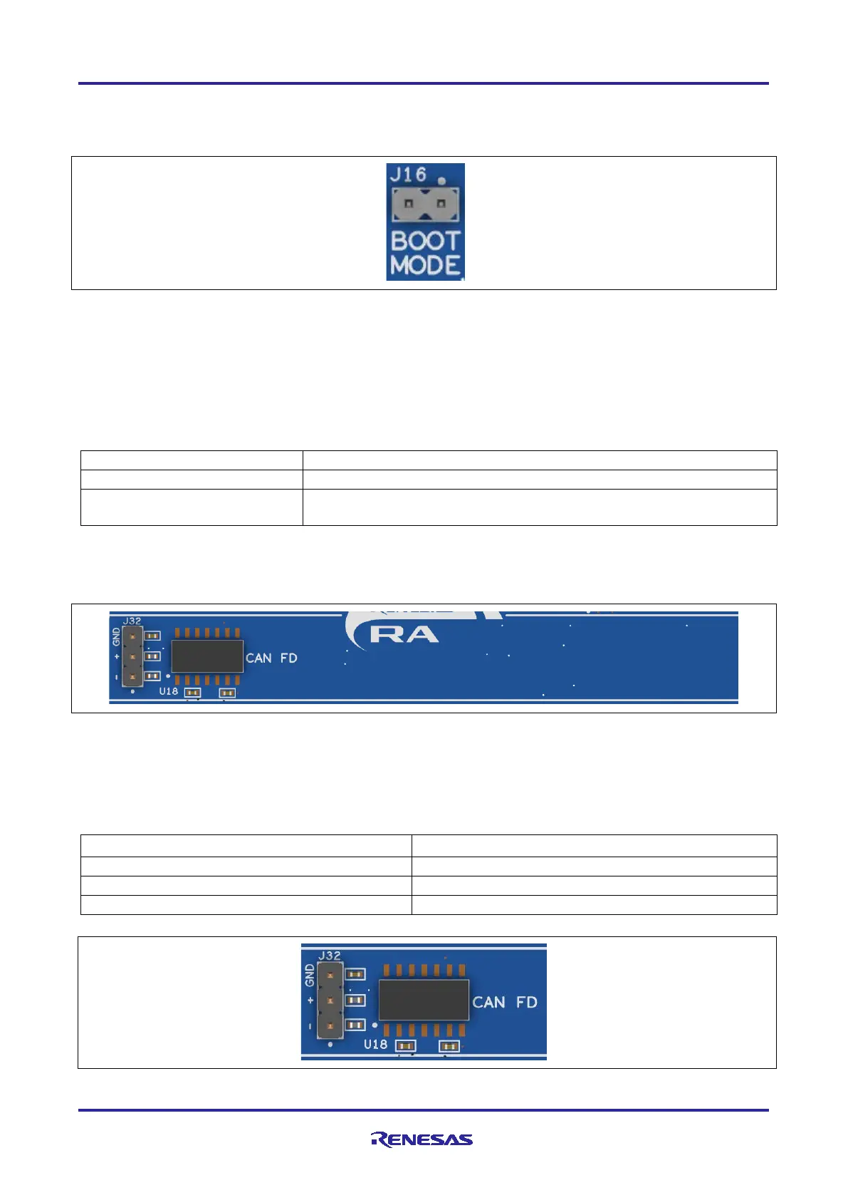
5.5.3 MCU Boot Mode
A two-pin header (J16) is provided to select the Boot mode (P201) of the RA MCU. For normal operation, or
Single-Chip mode, leave J16 open. To enter SCI Boot mode or USB Boot mode, place a jumper on J16.
Figure 20. Boot Mode
Note: The RA MCU fitted to the EK-RA4E2 board may not contain the latest version of the on-chip boot
firmware.
5.5.4 Crystals
If the main high-precision crystal oscillator is not needed, then the ports that it is connected to can be used
for other purposes.
Table 21. Main 20 MHz Crystal Selection
20 MHz Crystal Oscillator
E68 and E69 closed, E70 and E71 open
E68 and E69 open, E70 and E71 closed. P212 and P213 are available
for other purposes
6. Special Feature Access Area
The Special Feature Access area provides features specific to the RA4E2 MCU group such as CAN.
Figure 21. Special Feature Access Area
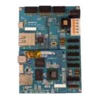
6.1 CAN Bus
The EK-RA4E2 board provides a CAN bus transceiver (TJA1043T,118) that is connected directly to the RA
MCU. External connection to the CAN bus is made using the 0.1” pitch 3-pin male header J32.
Table 22. CAN Bus Assignments
Figure 22. CAN Bus