Renesas RA Family EK-RA4E2 v1 – User's Manual
R20UT5175EG0300 Rev. 3.00 Page 24 of 30
Feb.27.23
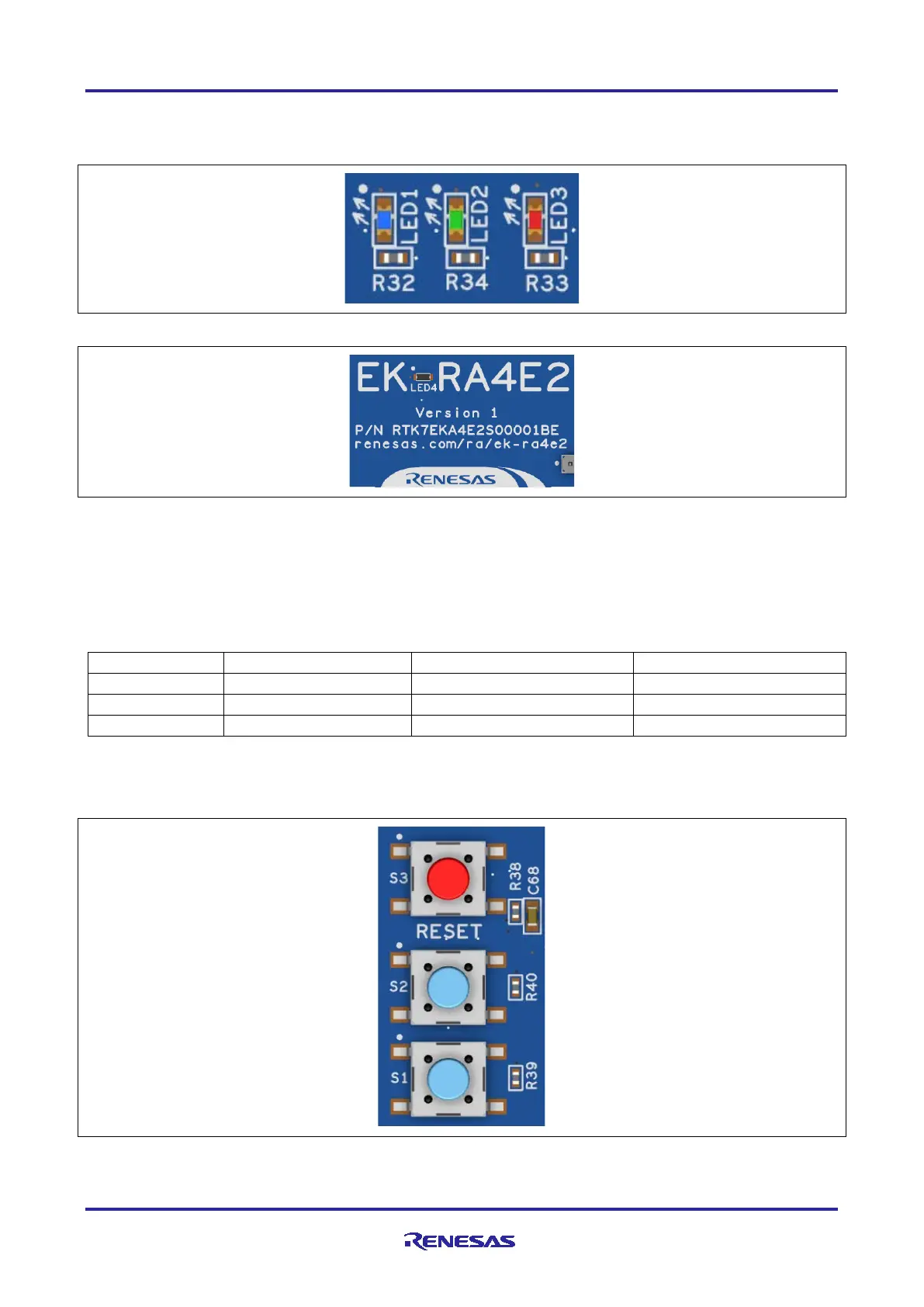
The user LEDs may be isolated from the main MCU so the associated ports can be used for other purposes.
To separate LED1 from P207, trace-cut jumper E27 must be open. To separate LED2 from P104, trace-cut
jumper E26 must be open. To separate LED3 from P112, trace-cut jumper E28 must be open.
Figure 17. User LEDs
Figure 18. Power LED
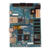
5.5.2 User and Reset Switches
Three miniature, momentary, mechanical push-button type SMT switches are mounted on the EK-RA4E2
board.
Pressing the reset switch (S3) generates a reset signal to restart the RA MCU.
Table 20. EK-RA4E2 Board Switches
The User Switches S1 and S2 may be isolated from the main MCU, so the associated ports can be used for
other purposes. To separate S1 from P005, trace-cut jumper E31 must be open. To separate S2 from P304,
trace-cut jumper E32 must be open.
Figure 19. Reset and User Switches