Renesas RA Family EK-RA4E2 v1 – User's Manual
R20UT5175EG0300 Rev. 3.00 Page 23 of 30
Feb.27.23
5.4 Connectivity
5.4.1 USB Full Speed
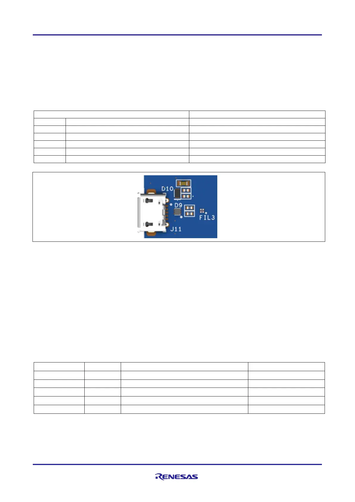
The USB micro-AB connection jack (J11) connects the RA MCU USB Full Speed interface to an external
USB interface, allowing communications for testing and use of the RA MCU firmware. This connection can
be configured as a USB device.
Connect a USB type-A female to micro-B male cable to J11. USB device cables can be connected to the
USB Full Speed port using this cable.
Table 18. USB Full Speed Connector
USB ID, jack internal switch, cable inserted
Figure 16. USB Full Speed Connector
5.4.2 I3C
The Arduino, mikroBUS, Grove, Qwiic, and Pmod 1 connectors connect the RA MCU I3C interface to
external I3C or I
2
C devices allowing communications between devices.
I
2
C bus pull-ups R11 and R41 are controlled by P206 and P205. When the bus is configured as I
2
C, then
these two pull-ups should be enabled by driving P205 and P206 high. When configured as I3C, then P205
and P206 should be set to high impedance (input). If P205 and P206 are required for other purposes, then
they can be isolated by cutting trace-cut jumpers E63 and E73 respectively.
5.5 Miscellaneous
5.5.1 User and Power LEDs
Five LEDs are provided on the EK-RA4E2 board.
Behavior of the LEDs on the EK-RA4E2 board is described in the following table.
Table 19. EK-RA4E2 Board LED Functions