Renesas RA Family Getting Started with Low Power Applications for RA6 and
RA4 Groups
R11AN0471EU0104 Rev.1.04 Page 32 of 40
Oct.1.21
7.5.3 Operable Long Timer
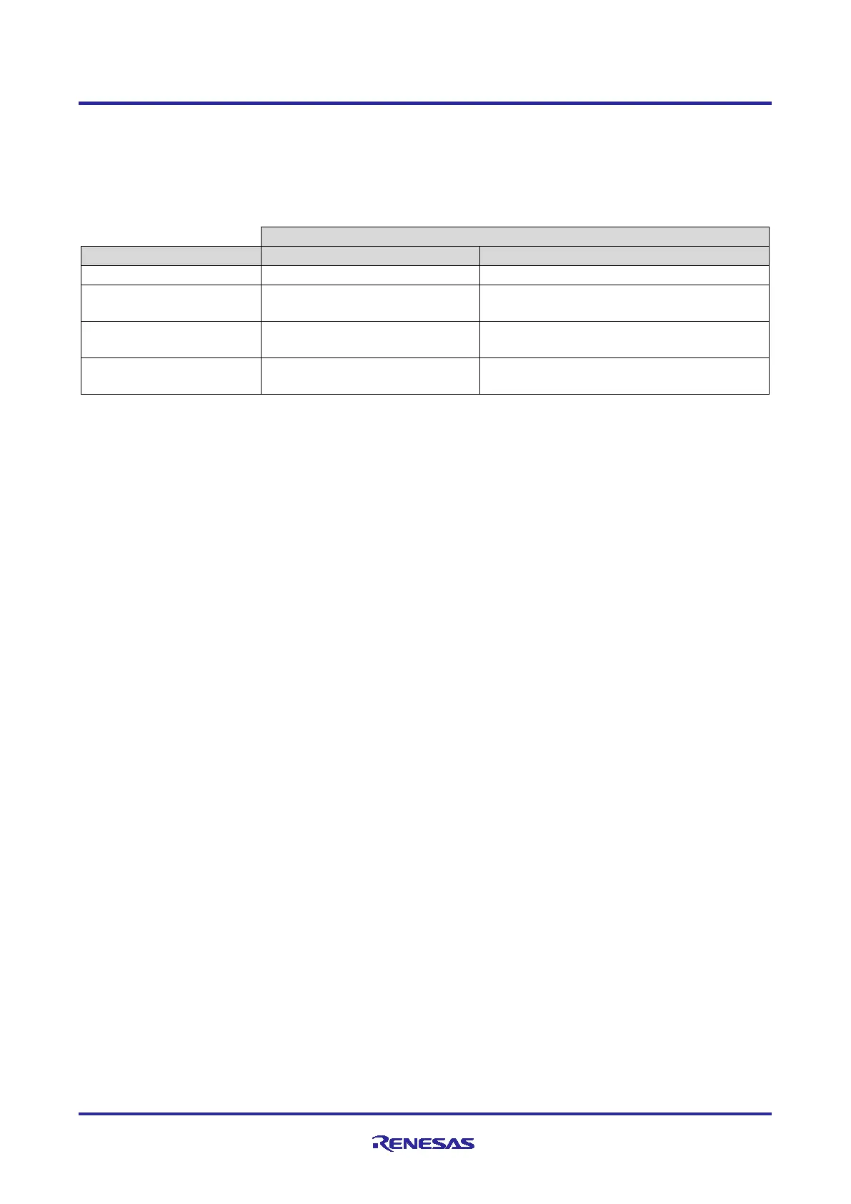
In the Operable Long Timer application, the user button is used to enter Software Standby and Deep
Software Standby modes from normal mode. AGT1 underflow interrupt is used to exit the LPM modes.
Table 10 shows the transition sequence and associated events used in the Operable Long Timer application.
Table 10. LPM Transition Table in Operable Long Timer Application
Enters Software Standby Mode
Exits the Software Standby mode and
enters the Normal Mode
(From Software Standby)
Enters Deep Software Standby
Mode
Exits the Deep Software Standby Mode
and resets the MCU
7.6 Measure MCU Current
The following steps are required to measure MCU current on EK-RA6M3, which is supported by the LPM
applications:
• Remove the R2 (resistor).
• Measure the voltage drops across R3 and calculate MCU current (Icc); replace R3 with a bigger resistor if
needed.
To measure the MCU current (Icc) directly, connect a multimeter between the +3V3 and +3V3_MCU pins on
the kit connectors after removing the R3 resistor.
To measure MCU current (Icc) on FPB-RA6E1 and FPB-RA4E1, replace R3 with a bigger resistor, measure
the voltage drops across R3, and calculate MCU current (Icc).
8. Migrating LPM Applications to Different MCU/Kit
Even though the LPM applications are created for the EK-RA6M3 kit, they are designed to easily migrate to
other Renesas RA Kits. Refer to Table 1 of this document for more details about the supported Renesas RA
kits. The following steps are basic procedure to port the project to supported Renesas RA kits.
Rename and import the projects to e
2
studio, for example, changing OLT_Timer_App_EK_RA6M3 to
OLT_Timer_App_EK_RA6M2 as shown in Figure 32.

 Loading...


