Renesas RA Family Getting Started with Low Power Applications for RA6 and
RA4 Groups
R11AN0471EU0104 Rev.1.04 Page 15 of 40
Oct.1.21
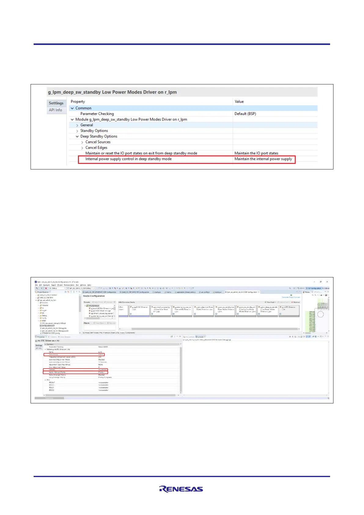
supply to most of the internal peripherals. For example, Maintain the internal power supply is needed to
keep AGT timer running in the Operable Long Timer application as shown in Figure 11.
This is the option used in this application example. For other available options, refer to the FSP User manual
and MCU Hardware user manual.
Figure 11. Internal Power Supply Selection in Deep Software Standby Mode
3.3.2 Timer Configuration
3.3.2.1 RTC Configuration
The Real Time Clock (RTC) is one of the peripherals which can operate in all the Low Power Modes. The
RTC is primarily used for time keeping, which updates the time independent of MCU in LPM. In this
application, the RTC is used for keeping track of the time in the Clock Changing and LPM Transition
application and to wake up from Software Standby mode via the RTC alarm interrupt. RTC uses the LOCO
as the clock source in the application.
The application displays the RTC time when the MCU transition from LPM to Normal mode. This gives the
indication of the how long the MCU was in LPM and latest time info.
The following Figure 12 shows the configurations of RTC for Time and Alarm. Alarm is used as trigger in the
LPM. The clock source of RTC is LOCO, which is available in Low Power Modes.
Figure 12. RTC Properties Configuration using the Properties Tab
3.3.2.2 AGT Timer Configuration
As mentioner earlier, the Operable Long Timer application in LPM uses AGT timer channel 0 (AGT0) and
AGT timer channel 1 (AGT1) in cascade mode to create a 10-second operable long timer. In this mode,
AGT0 underflow interrupt will trigger the counter of AGT1.

 Loading...


